6 front upstop wear pad check, 7 front upstop wear pad gap check, 8 front upstop wear pad shimming – Lull 944E-42 Service Manual User Manual
Page 251: Front upstop wear pad check -11, Front upstop wear pad gap check -11, Front upstop wear pad shimming -11, D section 11.3.6, “front upstop wear pad check.”), Section 11.3.6, Front upstop wear pad check.”)
11-11
944E-42
Transfer Carriage
11.3.6
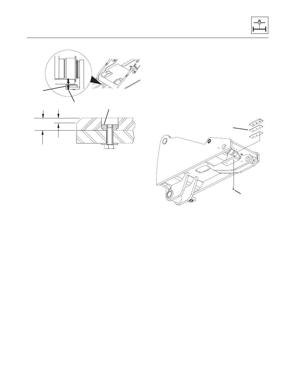
Front Upstop Wear Pad Check
The front upstop wear pads (5) are located under the
frame rails at the front of the transfer carriage.
Each wear pad is manufactured with a convenient wear
pad indicator. This is the angled cut at each end of all
wear pads.
The total thickness (6) of a new wear pad is 0.625 in
(16 mm). The angled cut will provide a total wear
thickness (7) of 0.25 in (6 mm). This will leave
approximately 0.375 in (10 mm) of total unused base
material.
The pads must never be worn past the angled cut
indicator because the metal pad insert (8), that holds the
pads in place, will begin to wear into the rail surfaces. If
the pad wears past this point, the metal insert in the pad
will begin to gouge the metal surfaces.
11.3.7
Front Upstop Wear Pad Gap Check
Note: The attachment should remain attached to the
quick attach for these checks.
1. Park the machine on a firm, level surface, level the
machine, fully retract the boom and transfer
carriage, level the boom, place the transmission
control lever in (N) NEUTRAL, engage the park
brake and shut the engine OFF.
2. Check the gap (9) between the top of the wear pad
and the bottom of the rail. The maximum gap should
be 0.12" (3 mm).
11.3.8
Front Upstop Wear Pad Shimming
1. Park the machine on a firm, level surface, level the
machine, fully retract the boom, level the boom,
place the transmission control lever in
(N) NEUTRAL, engage the park brake and shut the
engine OFF.
2. Place a Do Not Operate Tag on both the ignition key
switch and steering wheel, stating that the machine
should not be operated.
3. Open the engine cover. Allow the system fluids to
cool.
4. Properly disconnect the batteries.
5. Remove capscrews (10), shims, and front wear
pads (11). Label their position for later replacement.
Note: New shims have a 0.06 inch (1,5 mm) thickness.
6. Add new shims to the left and/or right side shim
groups as required to achieve proper gap
maximums. Spread shims evenly between the left
and right shim groups.
7. Coat the capscrews with Loctite
®
242 (blue). Replace
capscrews, shims, and front wear pads (11) in their
previously labeled positions. Torque the capscrews
to, 21 - 38 lb-ft (29 - 52 Nm).
8. Properly connect the batteries.
9. Close and secure the engine compartment cover.
OU1001
OU0991
5
6
7
8
9
MU1801
10
11