Lull 1044C-54 Series II Service Manual User Manual
Page 307
Frame Tilt and Oscillation
31200079
7-25
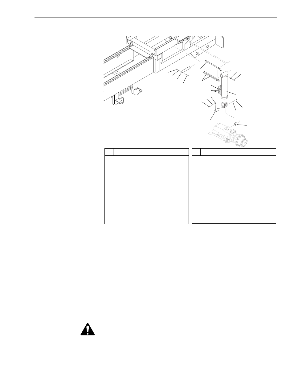
Removal
Fig. 7-17: Rear Oscillation Lock Cylinder Installation
(Ref. Fig. 7-17) The following steps are required to remove the rear
oscillation lock cylinder:
1. Follow preparation procedures as outlined in Section 3.
2. Place blocks between frame and top of rear axle. These will hold the
frame in place when the cylinder is removed.
3. Install brake pressure diagnostic port test gauge onto brake diagnostic
port.
4. While watching test gauge, press brake pedal numerous times until
pressure gauge reads 0 psi. Remove test gauge from diagnostic port.
5. Place a suitable drip pan under rear oscillation lock cylinder.
WARNING: Residual hydraulic pressure may be trapped in rear oscillation
lock cylinder. Wear proper eye and hand protection when
releasing pressure from cylinder. Hydraulic fluid under
pressure can be injected under skin or into eyes, resulting in
serious personal injury or death.
G
1025
15
14
13
9
4
2
8
20
19
18
6
5
1
2
3
4
16
View B
21
#
Description
1
Nut
2
Lockwasher
3
Upper Pivot Pin
4
Capscrew
5
#6 Hydraulic Hose
6
#8 Hydraulic Hose
7
Capscrew
8
Lock Pin
9
Lower Pivot Pin
10 Lockwasher
11 Nut
#
Description
12 Mounting Base
13 Grease Fitting
14 Grease Fitting Cover
15 Rear Carriage Tilt Cylinder
16 Check Valve
17 Wiring Harness
18 Grease Fitting Cover
19 Grease Fitting
20 Bushing
21 Pressure Reducing Valve