Lull 1044C-54 Series II Service Manual User Manual
Page 232
Boom and Transfer
6-90
31200079
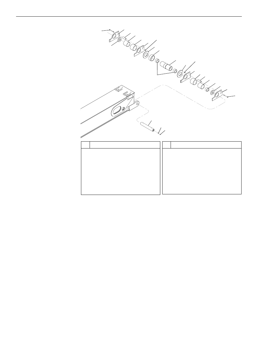
Fig. 6-95: Chain and Hose Guide Assembly
10. (Ref. Fig. 6-95) Install chain and hose guide assembly on rear of
middle (rear) boom section as follows:
a. Install two (2) roller bushings (Item 1) inside chain and hose roller
(Item 12) — one in each end.
b. Install hardened bushing (Item 11) and two (2) chain roller washers
(Item 10) on the chain and hose roller.
c. Install two (2) each left hand hose guides (Item 8), plastic bushings
(Item 7), hose spacers (Item 6), washers (Item 2), and right hand
hose guides (Item 4) on chain and hose roller.
d. Install two hose guide spacers (Item 5) between left and right hand
hose guides with two (2) lock nuts (Item 9) and capscrews (Item 3).
Torque the lock nuts to 180 in-lbs.
e. Install chain and hose roller assembly on rear of boom section with
chain and hose roller shaft (Item 13).
f.
Install two (2) grease fittings (Item 14) and grease fittings covers
(Item 15) on chain and hose roller shaft.
J
1238
13
14
15
2
3
4
5
6
7
8
10
11
12
10
4
3
7
5
6
2
8
9
9
1
1
#
Description
1
Roller Bushing
2
Washer
3
Capscrew
4
Right Hand Hose Guide
5
Hose Guide Spacer
6
Hose Spacer
7
Plastic Bushing
8
Left Hand Hose Guide
#
Description
9
Lock Nut
10 Chain Roller Washer
11 Hardened Bushing
12 Chain and Hose Roller
13 Chain and Hose Roller Shaft
14 Grease Fitting
15 Grease Fitting Cover