Lull 1044C-54 Series II Service Manual User Manual
Page 111
Supply, Pressure, and Return Hydraulics
31200079
5-29
7. Insert a new filter element into bowl. Lubricate bowl O-ring with
hydraulic oil and install it on bowl.
8. Screw bowl into filter head and tighten until snug.
Removal
Pressure Filter Assembly
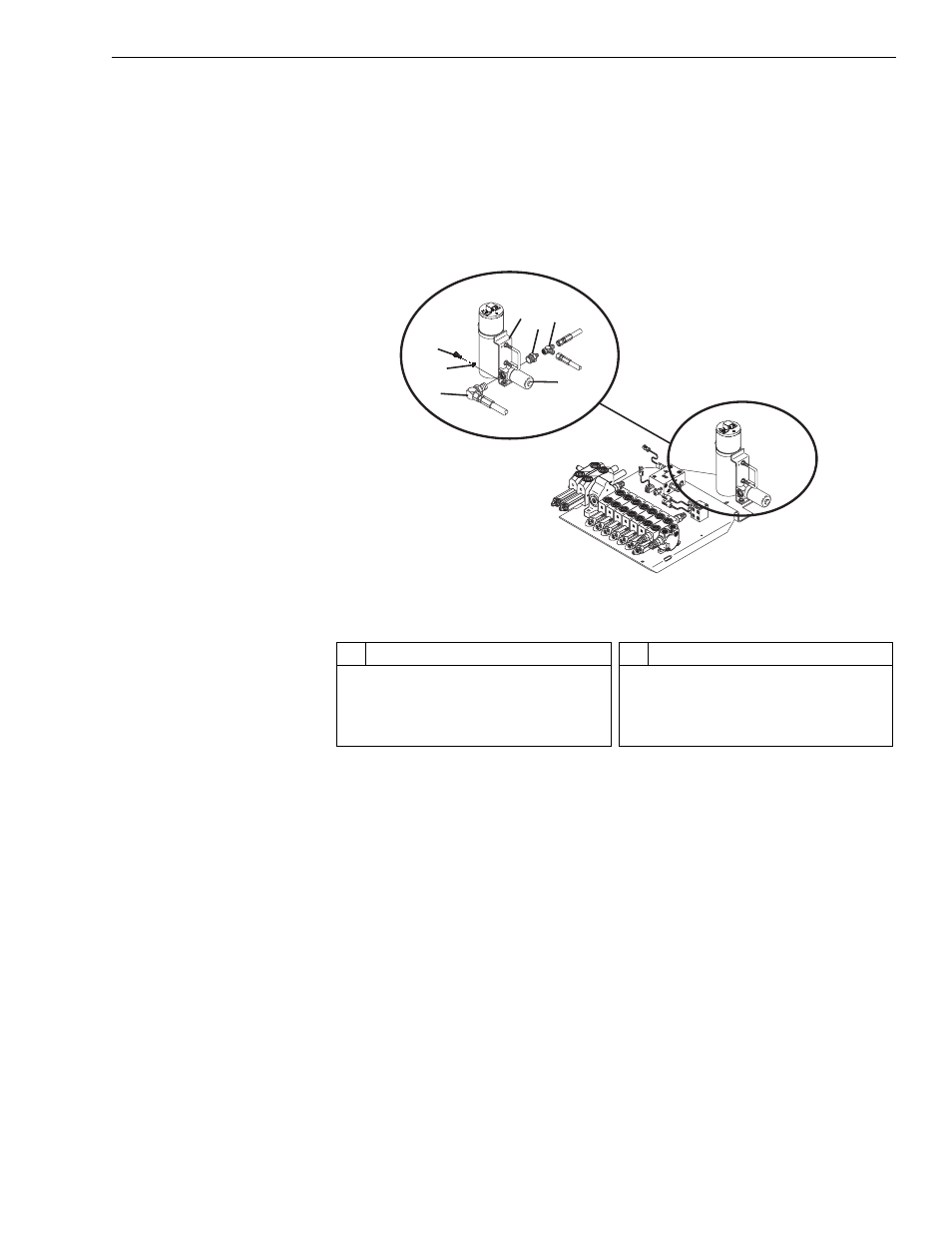
Fig. 5-20: Hydraulic Pressure Filter Assembly
(Ref. Fig. 5-20) The following procedure describes removal of the hydraulic
pressure filter assembly.
1. Follow preparation procedures as outlined in Section 3 of this manual.
Be sure to follow the guidelines in this section detailed under “General
Hydraulic Maintenance Practices” on page 5-3.
2. Clean the hydraulic pressure assembly to avoid contamination of the
system while removing the hydraulic pressure filter assembly.
3. Tag and
slowly loosen the three (3) fittings (Items 4, 6 and 7) from the
pressure filter assembly and bleed any remaining oil. Cap fittings.
4. While securing the hydraulic pressure filter assembly (Item 5), loosen
and remove the four (4) each capscrews (Item 2) and lockwashers
(Item 3) that connect the pressure filter assembly to the filter mounting
bracket (Item 1).
MV0050
1
6
5
2
3
4 7
#
Description
1
Filter Mounting Bracket
2
Capscrew
3
Lockwasher
4
90° O-Ring Hose Elbow
#
Description
5
Pressure Filter Assembly
6
90° O-Ring Hose Elbow
7
Swivel Tee