Lull 1044C-54 Series II Service Manual User Manual
Page 238
Boom and Transfer
6-96
31200079
c. Install auxiliary and front carriage tilt hydraulic tubes on channels
(Item 6) in inside of inner boom section with cushion clamps
(Item 3) as described in Substep d under Step 2 on page 6-68.
24. Install front carriage tilt cylinder in inner boom (See page 6-20).
25. Install auxiliary hydraulic quick disconnects
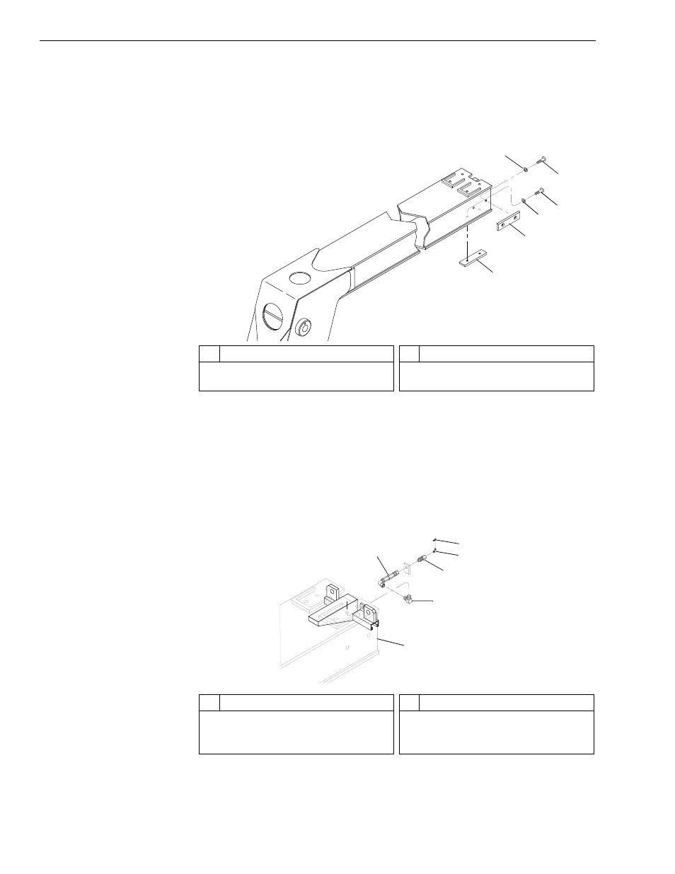
Fig. 6-101: Slide Pad Installation – Inner Boom Section
26. (Ref. Fig. 6-101) After applying thread locking compound to the
capscrews, install two (2) lower and two (2) side slide pads (Items 1
and 2) on inner boom section according to drawing specifications with
lockwashers (Item 3) and capscrews (Item 4). Torque capscrews to
180 in-lbs.
Fig. 6-102: Grease Hose Installation
J
1247
1
2
3
4
4
3
#
Description
1
Lower Slide Pad
2
Side Slide Pad
#
Description
3
Lockwasher
4
Button-Head Socket Capscrew
J
1
235
3
5
1
4
6
2
#
Description
1
Grease Hose
2
Inner Boom Section
3
Elbow
#
Description
4
Bulkhead Adapter
5
Grease Fitting
6
Grease Fitting Cover