Hydraulic pump, Installation, Description – Lull 1044C-54 Series II Service Manual User Manual
Page 112
Supply, Pressure, and Return Hydraulics
5-30
31200079
5. Remove the pressure filter assembly from the hole in the filter
mounting bracket.
Installation
Pressure Filter Assembly
(Ref. Fig. 5-20) The following procedure describes installation of the
hydraulic pressure filter assembly.
1. Insert the pressure filter assembly through the hole in the filter
mounting bracket, making sure that the bypass indicator is closest to
back of the mounting bracket.
2. Secure the pressure filter assembly to the mounting bracket with the
four (4) each capscrews and lockwashers. For final tightening, torque
the capscrews to 75 in-lbs.
3. Connect the three (3) fittings (Items 4,6 and 7) to the pressure filter
assembly. For final tightening, torque to 75–85 ft-lbs.
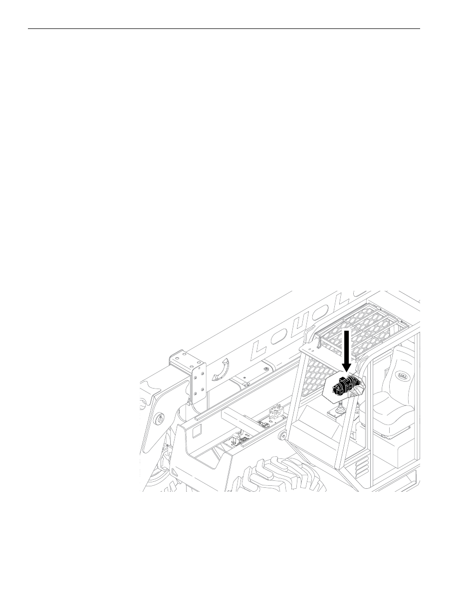
Hydraulic Pump
Description
Fig. 5-21: Hydraulic Pump Location
0
80
60
40
20
-20
K
1066