Lull 1044C-54 Series II Service Manual User Manual
Page 241
Boom and Transfer
31200079
6-99
Fig. 6-105: Upper Chain and Hose Reel Assembly – Middle (Forward) Boom
33. (Ref. Fig. 6-105) Install upper chains and hose reel assembly on
middle (forward) boom section as follows:
a. Install two (2) hose reels (Item 7) to rear of boom section with hose
reel pins (Item 10). Secure each pin to boom section with
lockwasher (Item 9) and capscrew (Item 8). Torque capscrews to
216 in-lbs.
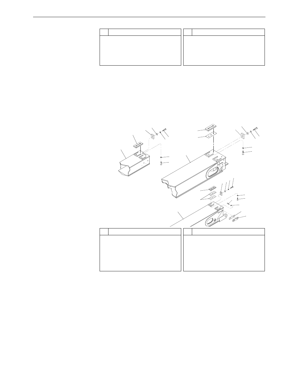
Fig. 6-106: Rear Slide Pad Installation
34. (Ref. Fig. 6-106) After applying thread locking compound to the
capscrews, install remaining slide pads (Items 2 and 12) and shims
(Item 10) on rear of boom sections with lockwashers (Item 7) and
capscrews (Item 8). Torque slide pad capscrews to 180 in-lbs.
Note: See “Shimming Procedures” on page 6-48 for details in
determining the number of shims that will be required when
performing Steps 34 and 37.
#
Description
1
Upper Chains
2
Lock Nut
3
Upper Chain Anchor
4
Capscrew
5
Lockwasher
#
Description
6
Chain Anchor Rod
7
Hose Reel
8
Capscrew
9
Lockwasher
10 Hose Reel Pin
J1
2
5
7
1
2
3
4
5
6
7
8
9
2
10
3
4
7
8
5
6
11
2
10
10
12
8
7
8
7
3 4
5
6
#
Description
1
Inner Boom Section
2
Upper Slide Pad
3
Slide Pad Retainer
4
Flatwasher
5
Lockwasher
6
Capscrew
#
Description
7
Lockwasher
8
Button-Head Socket Capscrew
9
Middle (Forward) Boom Section
10 Shim
11 Middle (Rear) Boom Section
12 Side Slide Pad