Lull 1044C-54 Series II Service Manual User Manual
Page 197
Boom and Transfer
31200079
6-55
4. (Ref. Fig. 6-57) Place a straight edge against the bottom surface of the
middle (forward) boom section. Measure the distance from the straight
edge to the bottom surface of the boom tube. This distance should not
exceed 1/4" (0.25"). The maximum deflection will be found just in front
of the middle (rear) boom section.
5. (Ref. Fig. 6-57) The side walls may also deflect outward at the window
areas. Take this measurement across the middle (forward) boom tube,
through the windows. Maximum allowable deflection is 3/16" (0.19")
per side. The maximum allowable middle (forward) boom tube width is
12-7/8" (12.875"), measured through the windows.
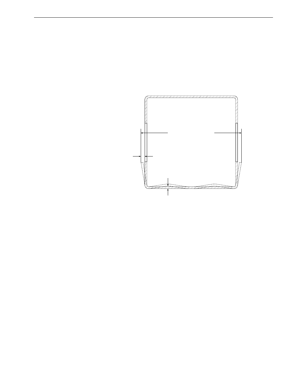
Fig. 6-58: Middle (Forward) Boom Cross-Section at Window
6. (Ref. Fig. 6-58) Place a straight edge against the bottom surface of the
middle (rear) boom section. Measure the distance from the straight
edge to the bottom surface of the boom tube. This distance should not
exceed 1/4" (0.25"). The maximum deflection will be found just in front
of the outer boom section.
7. (Ref. Fig. 6-58) The side walls may also deflect outward at the window
areas. Take this measurement across the middle (rear) boom tube,
through the windows. Maximum allowable deflection is 3/16" (0.19) per
side. The maximum allowable middle (forward) boom tube width is 14-
1/2" (14.5"), measured through the windows.
Boom Removal
4-Section Boom
1. Remove Quick Attach. See page 6-44.
2. Park machine on firm, level surface. If so equipped, fully retract transfer
carriage. Fully retract boom before lowering it to the ground.
3. Set park brake, lock shift selector in NEUTRAL position, shut off
engine and remove ignition key from switch. Block all wheels.
4. Position crane next to machine.
1/4" (0.25") Max.
3/16" (0.19")
J
1085
14 1/2" (14.5") Max.