Theory of operation and circuit logic, Frame tilt and oscillation – Lull 1044C-54 Series II Service Manual User Manual
Page 300
Frame Tilt and Oscillation
7-18
31200079
Theory of Operation and Circuit Logic
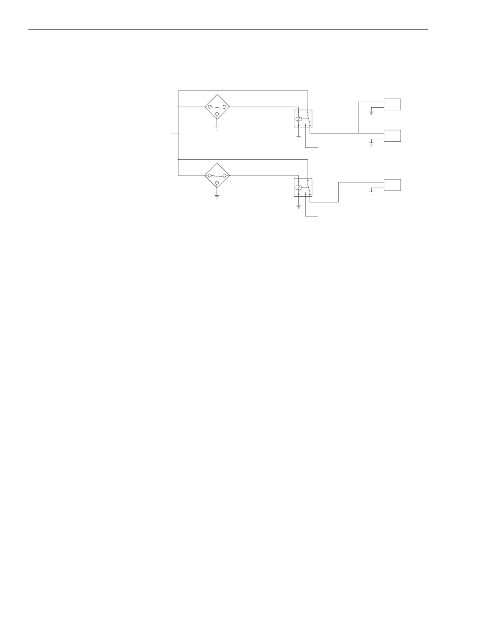
Fig. 7-11: Circuit Operation Below 40°
(Reference Fig. 7-11) Major components of the rear oscillation lock system
are:
1. Boom Over 20° Elevation Proximity Switch (S1)-senses when boom
position is above 20°.
2. Boom Over 40° Elevation Proximity Switch (S2)-senses when boom
position is above 40°.
3. Boom Over 20° Relay-receives signal from the Boom Over 20°
Elevation Proximity Switch (S1).
4. Boom Over 40° Relay-receives signal from the Boom Over 40°
Elevation Proximity Switch (S2).
5. Solenoid Valve (SV1)-controls frame tilt functions.
6. Solenoid Valve (SV2)-controls rear stabilizer cylinder along with
Solenoid Valve (SV3).
7. Solenoid Valve (SV3)-controls rear stabilizer cylinder along with
Solenoid Valve (SV2).
8. Service Brake Valve (not shown)-locks the rear stabilizer cylinder when
applied regardless of the status of SV2 and SV3.
MV0540
VALVE ON VALVE PLATE
REAR AXLE STABILIZER CONTROL
3-WAY SOLENOID VALVE ON
ON REAR STABILIZER CYLINDER
REAR AXLE STABILIZER VALVE
2-WAY SOLENOID VALVE ON
SOLENOID VALVE ON
REAR AXLE STABILIZER
CONTROL VALVE
S2
BOOM ANGLE GREATER THAN 40 - OPEN
BOOM ANGLE LESS THAN 40 - CLOSED
BOOM ANGLE LESS THAN 20 - CLOSED
BOOM ANGLE GREATER THAN 20 - OPEN
S1
OVER 40°
BOOM
86
30
87
87A
85
B
A
SV1
OVER 20°
BOOM
86
30
87
87A
85
RELAY
RELAY
FROM
FUSE PANEL
+12 VOLTS
B
A
SV3
B
A
SV2
TO ENABLE FOOT
SWITCH AND TO
DISABLE
TRANSMISSION
TO RESTRICT
TRANSMISSION
TO 1ST & 2ND
GEARS