Lull 1044C-54 Series II Service Manual User Manual
Page 303
Frame Tilt and Oscillation
31200079
7-21
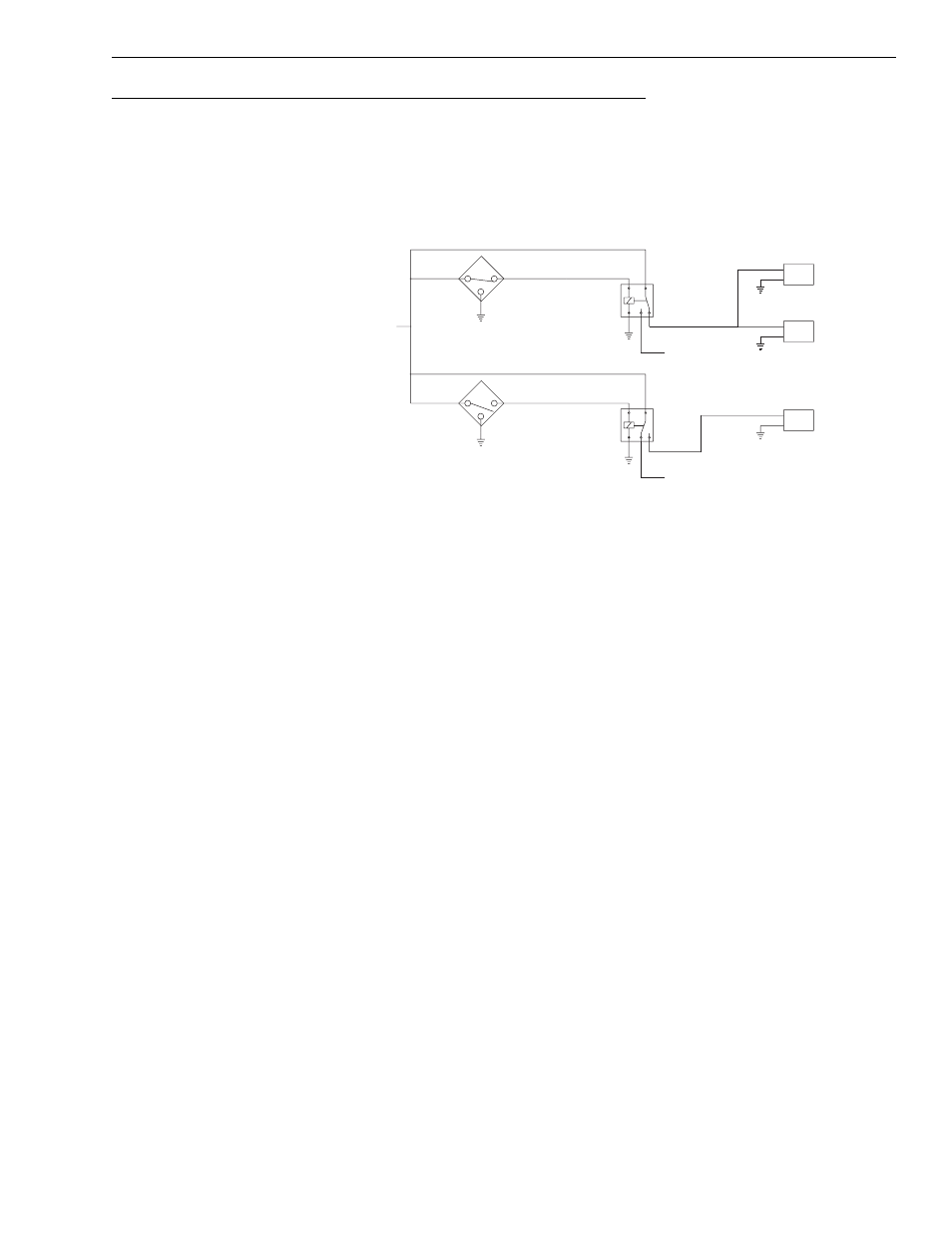
Boom Positioned Above 20° Below 40° With the Service Brake Applied
Fig. 7-14: Circuit Operation Above 20° Below 40° with Service Brake Applied
(Ref. Fig. 7-14) The following describes the rear axle stabilizer circuit logic
when the boom is positioned above 20° below 40° elevation with the
service brake applied.
1. When the boom is above 20° and below 40°, the proximity switch (S2)
is sensing the boom, so the (S2) proximity switch closes. Proximity
switch (S1) is not sensing the boom, so it opens when boom is above
20°.
2. When the proximity switch (S1) is open, the Boom Over 20° relay is not
energized and Solenoid Valve (SV1) is not energized, which restricts
the frame tilt.
3. Applying the service brake locks the rear stabilizer cylinder
hydraulically, which prevents the frame from rotating on the rear axle.
MV0570
VALVE ON VALVE PLATE
REAR AXLE STABILIZER CONTROL
3-WAY SOLENOID VALVE ON
(ENERGIZED)
ON REAR STABILIZER CYLINDER
REAR AXLE STABILIZER VALVE
2-WAY SOLENOID VALVE ON
(ENERGIZED)
SOLENOID VALVE ON
REAR AXLE STABILIZER
CONTROL VALVE
(NOT ENERGIZED)
S2
BOOM ANGLE GREATER THAN 40 - OPEN
BOOM ANGLE LESS THAN 40 - CLOSED
BOOM ANGLE LESS THAN 20 - CLOSED
BOOM ANGLE GREATER THAN 20 - OPEN
S1
OVER 40°
BOOM
86
30
87
87A
85
B
A
SV1
OVER 20°
BOOM
86
30
87
87A
85
RELAY
RELAY
FROM
FUSE PANEL
+12 VOLTS
B
A
SV3
B
A
SV2
NOT ENERGIZED
ENERGIZED
TO RESTRICT
TRANSMISSION
TO 1ST & 2ND
GEARS
TO ENABLE
FOOT SWITCH
AND TO
DISABLE
TRANSMISSION