Lull 1044C-54 Series II Service Manual User Manual
Page 291
Frame Tilt and Oscillation
31200079
7-9
Removal
Frame Tilt Cylinder
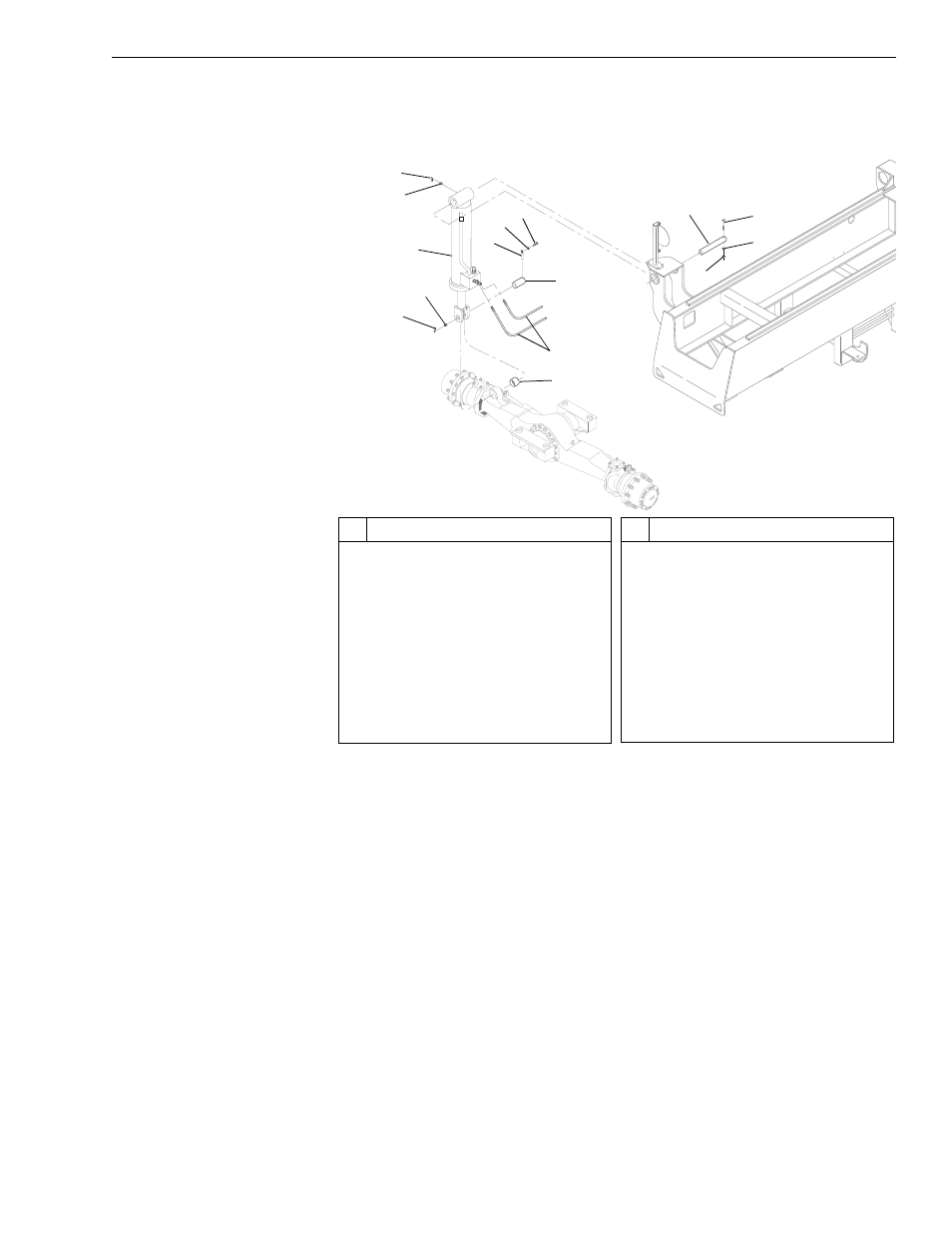
Fig. 7-6: Frame Tilt Cylinder Installation
(Ref. Fig. 7-6) The following procedures are required to remove the frame
tilt cylinder.
1. Follow preparation procedures as outlined in Section 3.
2. Place blocks between frame and top of front axle. These will hold the
frame in place when the cylinder is removed.
3. Tag and disconnect two (2) hydraulic hoses (Item 9) at frame tilt
cylinder (Item 3). Cap hoses and fittings.
4. See warning and procedures on page 7-15 for releasing hydraulic
pressure in cylinder.
5. Remove nut (Item 18), lockwasher (Item 17), and capscrew (Item 16)
securing cylinder upper pivot pin (Item 15) to frame.
6. Remove capscrew (Item 14), lockwasher (Item 12), and lock pin
(Item 11) securing cylinder lower pivot pin (Item 13).
G1
022
2
1
3
2
1
19
9
13
11
12
14
15
16
17
18
View B
#
Description
1
Grease Fitting Cover
2
Grease Fitting
3
Frame Tilt Cylinder
4
Capscrew
5
Mounting Block
6
Lockwasher
7
Nut
8
Shim
9
Hydraulic Hose
10 Mounting Block w/Lock Pin Hole
#
Description
11 Lock Pin
12 Lockwasher
13 Lower Pivot Pin
14 Capscrew
15 Upper Pivot Pin
16 Capscrew
17 Lockwasher
18 Nut
19 Lower Cylinder Bushing