J.P. Instruments EDM 700/800/711 Pilots Guide User Manual
Page 8
Page 4
Engine Data Management
A single EGT gauge merely gives you an average of each cylinder’s
temperature: some cylinders can be too rich, while others too lean.
Variations produced by differences in fuel distribution, ignition, and
compression will cause each cylinder to follow its own mixture and
temperature relationship such that one cylinder will reach peak before
another.
Section 2 - Displays and Controls
The EDM monitors engine temperatures and voltages, assists in
adjusting the fuel/air mixture, and helps diagnose engine malfunctions.
There are three components of the user interface:
Analog display including cylinder number and index dot
Digital display for numeric readouts and messages
Two front panel operating buttons.
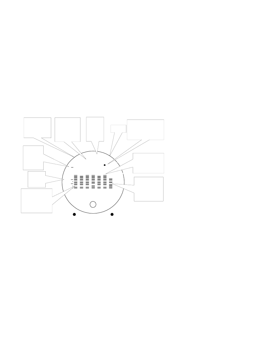
Displays
I340 376
STEP
LF
1
2
3
4
5
6
T
7 3
HP
NRM
F
EDM
800
JPI
_
EGT
%
Limit
_
250
350
450
CHT
TSO
°F or °C
Dash line or
NRM indicates
Normalize or
Percent view
Cylinder
numbers 1
through 6. T is
TIT otherwise
oil temp
Exhaust Gas
Temperature
(EGT) is the top of
the column
Percent
HP
or RPM
(EDM-
800 only)
Dot indicates which
cylinder temperatures
are shown in the
digital display
Cylinder Head
Temperature
(CHT) is shown
as a missing
segment
Maximum
line is the
EGT, TIT
and OIL
redline
CHT
absolute
scale
Systems with
both TIT and
OIL, OIL is
shown as
missing segment
Analog Display
The upper half of the face of the EDM is the analog display with %HP.
The following is a description of the analog display, from top to bottom.
Numbers in circles refer to features in the above diagram.