12 dash switches, 1 ignition key switch, Dash switches – SkyTrak 8042 Service Manual User Manual
Page 206: Ignition key switch
Electrical System
9-24
6036, 6042, 8042, 10042, 10054
9.12
DASH SWITCHES
Note: For information on the front windshield wiper, rear
window wiper and washer systems, refer to Section 9.8,
“Window Wiper/Washer Windshield Wiper Motor.”
9.12.1
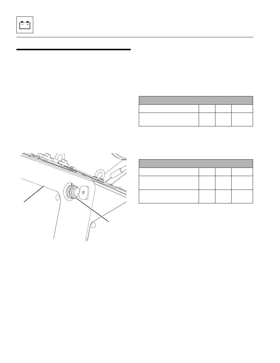
Ignition Key Switch
a. Ignition Switch Removal
1. Park the machine on a firm, level surface, level the
machine, fully retract the boom, lower the boom,
place the transmission control lever in
(N) NEUTRAL, engage the park brake and shut the
engine OFF.
2. Place a Do Not Operate Tag on the steering wheel,
stating that the machine should not be operated.
3. Open the rear door. Allow the system fluids to cool.
4. Properly disconnect the battery.
5. Remove the lower access panel (5).
6. From under the dash, remove the hex nut securing
the ignition key switch (6) to the dash.
7. Label and disconnect the ignition switch connectors
and remove the switch from the machine.
b. Disassembly
DO NOT disassemble the ignition switch. Replace a
defective switch with a new part.
c. Inspection and Replacement
To determine the proper operation of the ignition key
switch, test the terminals on the back of the switch for
continuity with an ohmmeter.
Test the ignition key switch for continuity, by checking
from the ignition (BLUE) wire to each of the following
wires in each corresponding switch position. Continuity
(X) should be present as indicated in the following chart:
Test the ignition key switch for continuity, by checking
from the ignition (RED) wire to each of the following wires
in each switch position. Continuity (X) should be present
as indicated in the following chart:
If all terminals do not show proper continuity, replace the
ignition switch.
d. Ignition Switch Installation
1. Connect the ignition key switch to the previously
labeled connectors.
2. The ignition switch has a drain hole located on the
shaft, between the backing nut and the face of the
ignition switch cylinder, behind the dash panel. Align
the ignition switch so that when it is in the OFF
position, the key slot is positioned vertically (straight up
and down) and the indicator mark for the drain hole,
is pointing down. Install the nut securing the ignition
switch to the dash. DO NOT overtighten.
3. Install the lower access panel.
4. Properly connect the battery.
5. Remove the Do Not Operate Tags from both the
ignition key switch and the steering wheel.
6. Close and secure the rear door.
Note: If further information is needed, refer to Section
9.5, “Electrical System Schematics.”
MAQ0270
5
6
Switch Position
Test from BLUE wire to:
OFF
RUN
START
WHT Wire, Pin B on 3 Pin
Connector
X
Switch Position
Test from RED wire to:
OFF
RUN
START
PUR Wire, Pin B on 5 Pin
Connector
X
X
RED/BLK Wire, Pin C on 5
Pin Connector
X
X