8 outrigger valve (10042 & 10054 only) – SkyTrak 8042 Service Manual User Manual
Page 174
Hydraulic System
8-30
6036, 6042, 8042, 10042, 10054
8.7.8
Outrigger Valve (10042 & 10054 only)
The outrigger valve allows the left and right outriggers to
be raised or lowered depending on the position of the
outrigger switches located on the side console in the cab.
Verify the correct operation of the outrigger valve
solenoids before considering replacement of the valve.
a. Outrigger Valve Removal
1. Park the machine on a firm, level surface, level the
machine, fully retract the boom, raise the boom, place
the transmission control lever in (N) NEUTRAL,
engage the park brake and shut the engine OFF.
2. Place a Do Not Operate Tag on both the ignition key
switch and the steering wheel, stating that the
machine should not be operated.
3. Temporarily block up or support the raised boom.
4. Open the rear door. Allow the system fluids to cool.
5. Properly disconnect the battery.
6. Remove the transmission covers.
7. Label, disconnect and cap the hydraulic hoses and
the electrical plugs connected to the outrigger valve.
8. Remove the two flange nuts and two carriage bolts
securing the outrigger valve to the frame. Remove
the outrigger valve from the machine.
9. Wipe up any hydraulic fluid spillage in, on, near and
around the machine, work area and tools.
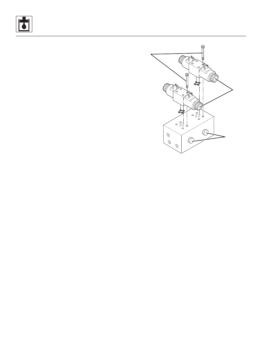
b. Outrigger Valve Disassembly, Cleaning,
Inspection and Assembly
1. Place the outrigger valve assembly on a suitable
work surface.
2. Remove the solenoid valve assemblies (2) from the
outrigger valve by removing the four capscrews (3).
Discard the four o-rings.
3. Remove the shuttle cartridges (4) from the outrigger
valve.
4. Clean all components with a suitable cleaner before
inspection.
5. Inspect the solenoid cartridges for proper operation.
Check by shifting the spool to ensure that it is
functioning properly. Check that the spring is intact.
Inspect the cartridge interior for contamination.
6. Inspect internal passageways of the outrigger valve
for wear, damage, etc. If inner surfaces of the valve
DO NOT display an ultra-smooth, polished finish, or
components are damaged in any way, replace the
valve or appropriate part. Often, dirty hydraulic fluid
causes failure of internal seals and damage to the
polished surfaces within the secondary function
manifold.
Note: ALWAYS replace seals, o-rings, gaskets, etc.,
with new parts to help ensure proper sealing and
operation. Lubricate seals and o-rings with clean
hydraulic oil.
7. Install the shuttle cartridges into the outrigger valve.
Torque to 35 lb-ft (48 Nm).
8. Attach the solenoid assemblies to the outrigger
valve using four new, oiled o-rings and the
previously used capscrews.
P
S
T
MH3881
2
3
4