5 windshield wiper assembly, 6 heater/defroster system (if equipped), Windshield wiper assembly – SkyTrak 8042 Service Manual User Manual
Page 101: Heater/defroster system (if equipped)
4-7
6036, 6042, 8042, 10042, 10054
Cab and Covers
• Move the joystick handle to the left, activating the
frame sway function. The boom should SWAY LEFT.
Auxiliary Control Joystick
• Move the joystick handle to the right, the auxiliary
attachment should LOWER/OPEN.
• Move the joystick handle to the left, the auxiliary
attachment should RAISE/CLOSE.
6. Install console panel in the cab.
7. Install the transmission covers.
4.3.5
Windshield Wiper Assembly
Refer to Section 9.8, “Window Wiper/Washer Windshield
Wiper Motor,” for removal and installation information.
4.3.6
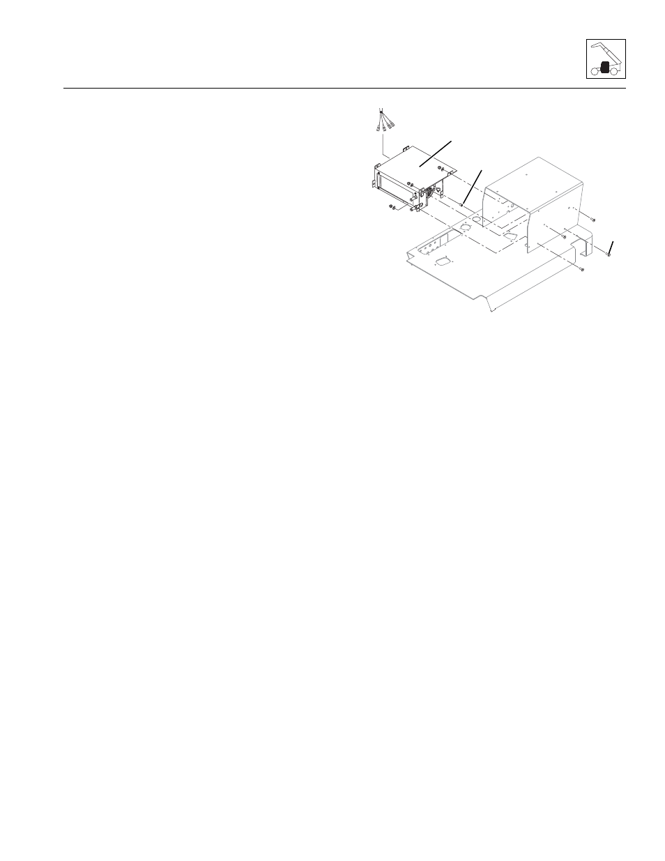
Heater/Defroster System (If Equipped)
a. Heater Assembly Removal
1. Park the machine on a firm, level surface, level the
machine, fully retract the boom, lower the boom,
place the travel select lever in the (N) NEUTRAL
position, engage the park brake and shut the engine
OFF.
2. Place a Do Not Operate Tag on both the ignition key
switch and the steering wheel, stating that the
machine should not be operated.
3. Open the rear door. Allow the system fluids to cool.
4. Properly disconnect the battery.
5. Place a suitable container beneath the radiator drain
plug or petcock. Slowly turn the radiator cap to the
first stop, and allow any pressure to escape.
Remove the radiator cap.
6. Place a funnel at the base of the radiator to channel
the drained coolant into the container. Loosen the
drain plug or petcock and allow the coolant to drain.
7. Transfer the coolant to a container with a cover, and
label as “Used Antifreeze.” Dispose of the used
coolant at an approved recycling facility.
8. Close the radiator drain plug or petcock.
9. Remove the heater access panel.
10. Label, disconnect and cap the heater hoses. Pull the
hoses through the grommets.
Note: The capscrew (6) at the lower rear position on
each side of the heater will be secured with an insert nut
(7).
11. Remove the eight capscrews, six nuts and six
lockwashers.
12. Carefully pull the heater assembly forward. Label
and disconnect the wiring harness connections at
the blower.
13. Remove the heater assembly (8).
14. If the heater assembly is to be replaced: Remove
the four hex-slotted capscrews, and remove the
mounting bracket from the heater assembly.
b. Heater Assembly Installation
1. Connect the wiring harness connections to the
blower.
Note: The capscrew (6) at the lower rear position on
each side of the heater will be secured with an insert nut
(7).
2. Slide the heater/mounting bracket assembly (8) into
the seat riser, and secure with the eight capscrews,
six lockwashers and six nuts.
3. Pull the hoses through the grommets. Uncap and
connect the previously labeled hoses to the heater.
4. Install the heater access panel and secure with the
previously used hardware.
5. Fill the cooling system completely with coolant,
allowing time for the coolant to fill the engine block.
The cooling system capacity is listed in Section 2.4,
“Fluid and Lubricant Capacities.”
6. Properly connect the battery.
MA8371
7
6
8