2 secondary function manifold, Secondary function manifold – SkyTrak 8042 Service Manual User Manual
Page 169
8-25
6036, 6042, 8042, 10042, 10054
Hydraulic System
f.
Main Control Valve Installation
1. Install the main control valve onto the frame, aligning
the bolts with the holes in the end sections of the
main control valve. Slide the main control valve into
position, and tighten the bolts.
2. Prime the main control valve by filling the inlet
openings with fresh, filtered hydraulic oil from a
clean container, before attaching the hoses.
3. Use new oiled o-rings as required. Uncap and
connect all previously labeled hoses, clamps, etc. to
the main control valve.
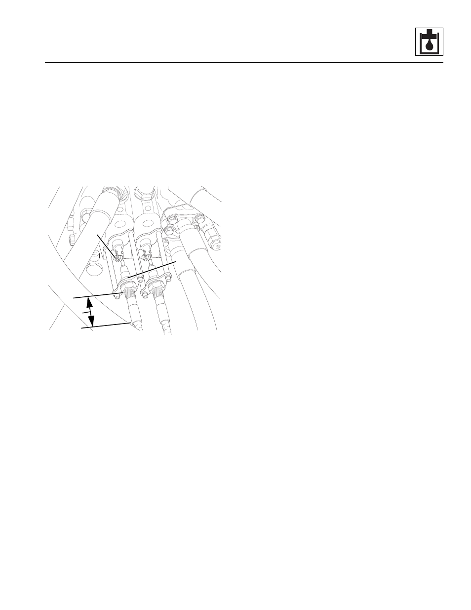
4. Connect the control cables to the main control valve:
a. Slide the outer jam nut (7) over the end of the
control cable, and install the cable in the bracket
with one nut on either side of the bracket. DO
NOT tighten the jam nuts at this time.
b. Connect the end of the cable to the shaft from
the control valve. Secure with an anchor pin and
spring pin (8).
c. Adjust the jam nuts until the distance (9) from the
outer jam nut to the end of the ferrule is the same
as recorded during removal. Tighten the jam
nuts.
d. Repeat steps for remaining control cables.
5. Check the routing of all hoses, wiring and tubing for
sharp bends or interference with any rotating
members, and install tie wraps and/or protective
conduit as required. Tighten all tube and hose
clamps.
6. Fill the hydraulic fluid reservoir. Refer to Section
8.5.2, “Hydraulic Oil Reservoir Filling.”
7. Start the engine and run at approximately one-third
to one-half throttle for about one minute without
moving the machine or operating any hydraulic
functions.
8. Inspect for leaks and check the level of the hydraulic
fluid in the reservoir. Shut the engine OFF.
Note: Check for leaks and repair as required before
continuing. Add hydraulic fluid to the reservoir as needed.
9. Wipe up any hydraulic fluid spillage in, on, near and
around the machine, work area and tools.
10. Install the transmission covers.
11. Close and secure the rear door.
g. Main Control Valve Test
Conduct a pressure check of the hydraulic system in its
entirety. Adjust pressure(s) as required. Refer to Section
8.3.1, “Pressure Checks and Adjustments.”
8.7.2
Secondary Function Manifold
The secondary function manifold is a directional control
valve. Hydraulic oil from the pump flows into the
secondary function manifold where the pressure is
reduced before the oil is directed to the power steering
unit or the park brake.
The secondary function manifold is a machined block
with the ports for two pressure reducing valves, a
pressure relief valve, two park brake solenoid valves (one
normally open and one normally closed), a check valve
and diagnostic test nipples. The secondary function
manifold is secured on the left side of the frame with two
carriage bolts and two hex flange nuts.
Verify the correct operation of the solenoids before
considering replacement of the secondary function
manifold. The manifold itself is not serviceable and must
be replaced if defective.
Note: DO NOT loosen, disassemble or attempt to adjust
any of the pressure valves unless specifically instructed
by the manufacturer to do so. Tampering with a pressure
valve will irrevocably alter pressure in the affected
circuits.
MA8482
8
9
7