2 isolation coupler installation, Isolation coupler installation – SkyTrak 8042 Service Manual User Manual
Page 143
7-11
6036, 6042, 8042, 10042, 10054
Engine - Cummins QSB3.3T/QSB4.5T
a jack under the bell housing (use a wood block to
support the engine) and carefully lift the engine until the
bottom edge of the bell housing is at the top edge of the
frame member that mounts the rear axle to the frame.
Watch the fan-to-radiator clearance as your are lifting the
engine. If necessary, turn the fan slightly by hand to gain
additional clearance.
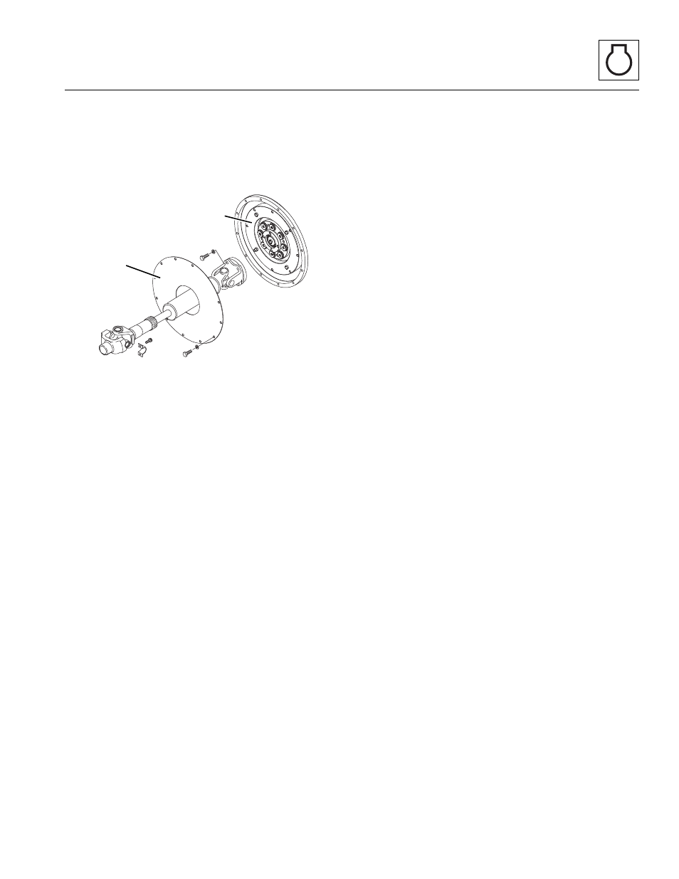
7. Remove the capscrews and lockwashers securing
the outer half of the coupler (8).
8. Remove the capscrews securing the small access
cover.
9. Remove the capscrews and locknuts securing the
coupler (9) to the flywheel. Turn the engine by hand,
using the fan belt, until the capscrews line up with
the access hole.
10. At this time, use a suitable cleaner/solvent and
thoroughly clean the mounting lip of the flywheel.
Wipe any debris from the inside of the bell housing.
Use the cleaner to clean the threaded holes around
the flange of the bell housing.
7.10.2
Isolation Coupler Installation
1. Use cleaner to clean the backside of the coupler,
where it comes in contact with the flywheel.
Note: The new coupler is heavy and requires two
people, one on each side, to install.
2. Place the new coupler into the indentation of the
flywheel and use new hardware to secure the
coupler to the flywheel.
3. Insert one capscrew into the access hole on the rear
right side of the bell housing and through the
flywheel and coupler. Assemble a new locknut onto
the capscrew. DO NOT fully tighten at this time.
4. Turn the flywheel 180° and insert another capscrew
and assemble with another new locknut. DO NOT
fully tighten until all capscrews and locknuts are in
place.
5. After all capscrews are in place, check to be sure the
coupler is resting squarely in the indentation of the
flywheel. Torque all the capscrews to 37 lb-ft
(48 Nm).
6. Install the small access cover plate to the right side
of the engine and tighten the hardware securely.
Note: Before assembling the drive shaft to the coupling;
be sure the access cover plate is placed on the engine-
side of the frame member that mounts the rear axle to
the frame.
Note: Apply Loctite
®
242
TM
threadlock compound to all of
the capscrews used during assembly.
7. Install the access cover plate over the drive shaft
and assemble the drive shaft flange to the coupler
using new hardware. Torque to 48 lb-ft (65 Nm).
8. If engine mounts were previously removed or
loosened, carefully lower the engine down onto the
front engine mounts. Reassemble the rebound
washer and secure in place with a new locknut.
Torque to 60 lb-ft (81 Nm). Repeat this procedure for
the engine mount on the other side.
9. Thoroughly clean the transmission yoke and secure
in place with new straps and hardware. Torque to
55-60 lb-ft (75-81 Nm).
10. After the drive shaft is in place, grease both u-joints
and the slip joint using multi-purpose grease.
11. Properly connect the battery.
12. Close and secure the rear door.
13. Remove the Do Not Operate Tags from both the
ignition key switch and the steering wheel.
MH6360
8
9