Figure 6-9: mechanical seal assembly, Caution – Hale SMR User Manual
Page 92
Maintenance and Repair
6-14
Stainless Max Series Pumps
1. First, review preceding section “Before You Begin...,” beginning
on page 6-1.
2. Remove the front clearance ring, the impeller and the rear wear
ring as described in the previous sections, beginning on page
6-9. The mechanical seal assembly is then exposed.
CAUTION!
MECHANICAL SEALS ARE PRECISION ENGINEERED DEVICES.
EXTREME CARE MUST BE TAKEN TO ENSURE THAT NO DAMAGE
OCCURS TO THE MATING FACES. ENSURE THAT THE FACES ARE
ABSOLUTELY CLEAN THROUGHOUT THE ENTIRE INSTALLATION.
SOLID FACES MUST BE CLEANED WITH AN APPROPRIATE
DEGREASER AND A SOFT CLOTH.
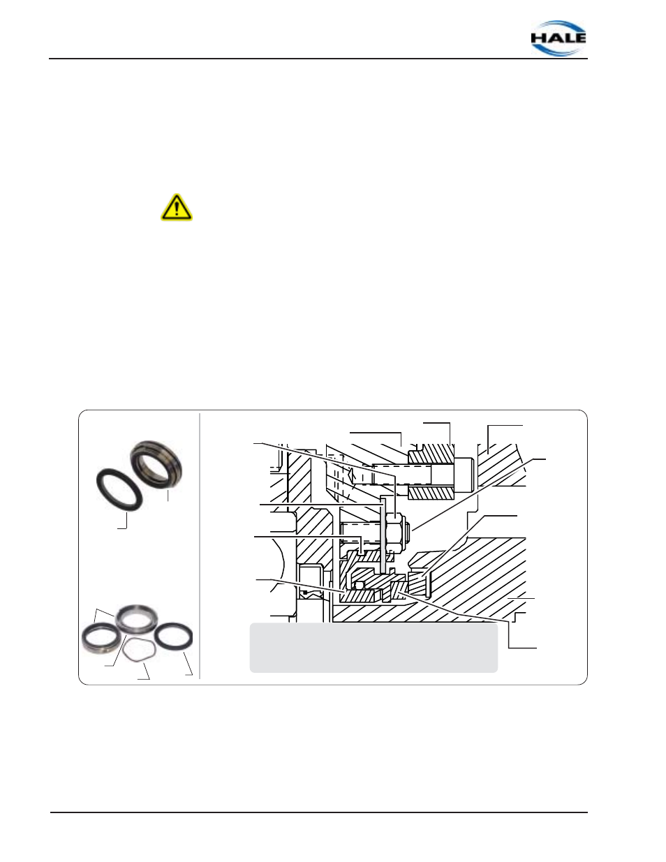
3. Remove the seal head assembly from the pump body by remov-
ing the two nyloc-nuts and washers. To remove the washers,
you must gently remove the seal head assembly at the same
time, being careful not to lose the wave washer (spring). See
Figure 6-9: “Mechanical Seal Assembly.”
Note: The stationary carrier may only by left in place if the wearing
faces are the only replacements being made.
Figure 6-9: Mechanical Seal Assembly
Impeller
Wear Ring
Rear Cover Plate
(Pump Body)
Nyloc-Nut
Seal
Retaining
Washer
Impeller
Pump/Impeller Shaft
Mating Ring
Assembly
Carbon
Face
O-ring
Seal
Seal Head
Assembly
Stud (2)
Seal
Assembled
Seal
Disassembled
Mating
Ring
Seal Head
Assembly
Wave Washer
Seal Head
Assembly
Mating
Ring
O-ring
Seal