Shift cylinder assembly, Figure 6-18: shift cylinder assembly, Removal – Hale SMR User Manual
Page 118
Maintenance and Repair
6-40
Stainless Max Series Pumps
Shift Cylinder Assembly
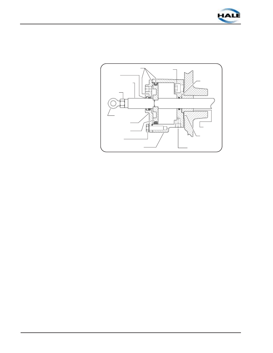
See Figure 6-18: “Shift Cylinder Assembly.”
Removal
1. Pull the shift rod into PUMP position (out). Loosen the lock nut
and remove rod end and nut from end of shift shaft.
2. Dismantle the cylinder cap - four screws marked (A).
3. Remove cylinder cap and O-ring seal.
4. Using a seal pick, remove the scraper and seal ring from the
cap.
5. Unscrew and remove the extension shaft.
6. Remove the piston from shaft, then remove seal rings.
7. Unscrew two screws, marked (B), then remove the cylinder
and gasket.
8. Remove seal ring from shift cylinder.
9. Remove and check bushing for wear. Replace accordingly
with Hale p/n: 250-9550-00-0.
Figure 6-18: Shift Cylinder Assembly
Rod End
Lock Nut
Extension Shaft
Spacer
Seal Rings (3)
Piston
Cylinder Cap
Screws (A)
Shift Cylinder
Air Inlet Port
1/8” NPT
Gasket
Bushing
Seal Ring
Screws (B)