Figure 6-17: lower housing assembly, Sliding gear shaft assembly, See figure 6-17: “lower housing assembly – Hale SMR User Manual
Page 115
Stainless Max Series Pumps
6-37
Maintenance and Repair
❑
Pay attention to section “Cleaning and Inspection Guidelines,”
beginning on page 6-6 to ensure a thorough installation.
❑
Make sure the needle bearing is in place (over the male end of
the sliding gear) before sliding the tail shaft assembly into
position.
❑
Rotate the sliding gear shaft and manually shift the gearshift to
check for proper operation - spins and slides freely.
❑
Refer to the previous sections to rebuild the top portion (upper
housing assembly) of the gearbox.
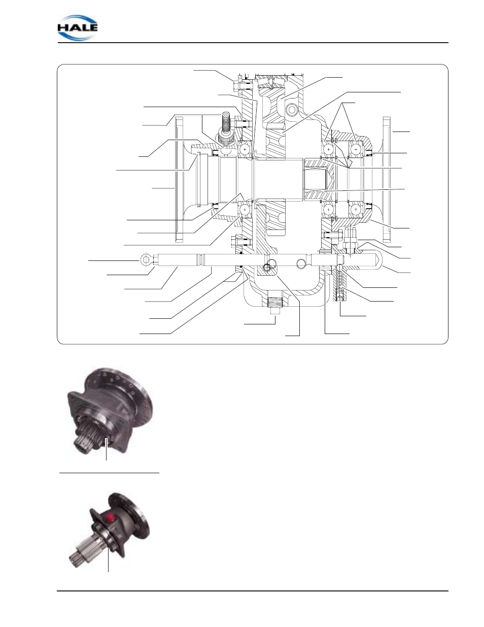
Sliding Gear Shaft Assembly
See Figure 6-17: “Lower Housing Assembly.”
Notes: If only the sliding shaft assembly is removed, shift the
gearshift mechanism to engage the sliding gear (PUMP position). The
sliding tail shaft assembly and the shift cylinder assembly need not be
removed.
Screw, Hold-Down
(Intermediate Shaft)
Intermediate Gear
Assembly
Sliding Gear
Assembly
Bearings
(Inner and Outer)
Retaining
Rings (4)
Tail Shaft
Oil Seal
Needle
Bearing
Rear Bearing
Cap
Switch
Seal Ring
Slide Gear Shaft
Gasket
Speed Counter Option,
with Bushing
(or Plug & Seal)
Front Bearing Cap
Slinger
Bearing
Oil Seal
Retaining Ring
Rod End
Lock Nut
Rod Extension
Flange and Gasket
Shifting Rod
O-ring Seal
Oil Drain Nut
(Magnetic)
Shift Fork
Nylon Set Screw,
Gearshift
Ball
Spring
Bearing
Figure 6-17: Lower Housing Assembly
Gearshift
Cap
Tail Shaft Assembly
Outer Retaining Ring
Sliding Shaft Assembly
Outer Retaining Ring
Retaining Ring