Pressure control, The p relief valve system, Figure 2-15: relief valve system arrangement – Hale SMR User Manual
Page 27
Stainless Max Series Pumps
2-13
Introduction
When the handle on the PVG is pulled out, the valve opens and
the switch energizes the primer motor. See Figure 2-14: “PVG
Priming Valve” on page 2-12. Pushing the handle de-energizes
the motor and closes the valve.
Pressure Control
The P Series relief valve system is a bronze, variable-pressure
setting relief valve that prevents undue pressure per the require-
ments of NFPA Standard 1901. An indicator light on the operator
control panel signals when the valve is open.
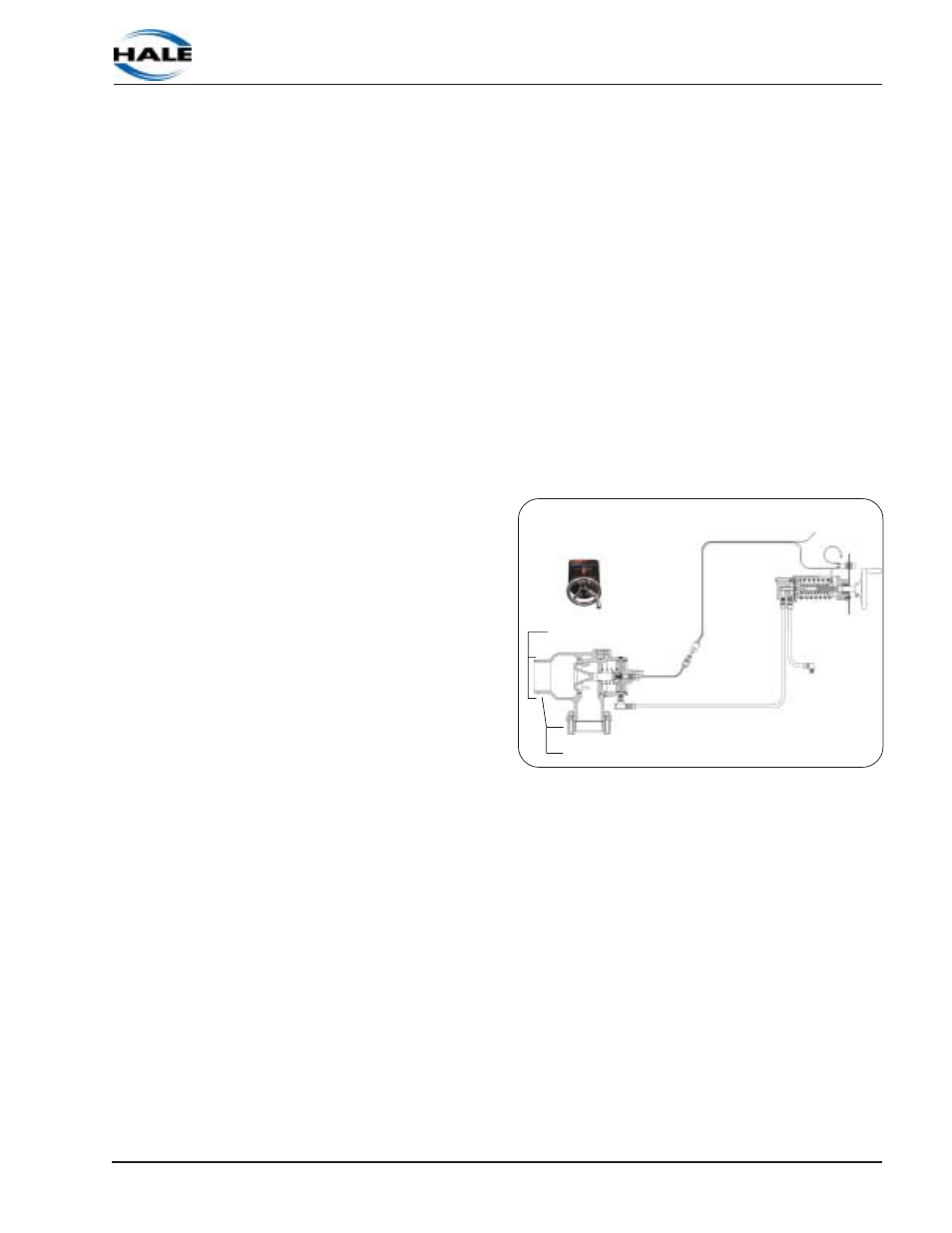
The P Relief Valve System
The P relief valve system consists of a panel mounted control
valve (PM)
and, depending
on the pres-
sure rating of
the pump, a
P30 or P35
relief valve.
The valve is
mounted in the
discharge
piping and
plumbed back
to the pump
suction. See
Figure 2-15: “P
Relief Valve
System Ar-
rangement.”
Valve connections are either flanged or Victaulic
™
. Both are
shown in Figure 2-15: “Relief Valve System Arrangement.”
How the relief system works:
A bleeder line mounted in the pump discharge pressure tap
provides pressure to the diaphragm in the PM control valve.
The hand wheel on the PM control either increases or de-
creases the spring tension on the diaphragm. The seat of the P-
series relief valve is kept closed by pump discharge pressure.
As the pump pressure increases, more pressure is applied to
the diaphragm in the PM Control valve.
Figure 2-15: Relief Valve System Arrangement
PM Control Valve
PM Control Panel
Victaulic
Flange