Relief valve test, Figure 4-1: pm valve control, Priming system test – Hale SMR User Manual
Page 55: Governor test
Stainless Max Series Pumps
4-3
Preventive Maintenance
Relief Valve Test
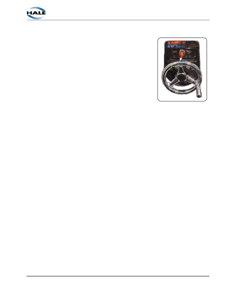
When the relief valve is not in opera-
tion, keep the hand wheel set above
the normal operating pressure.
1. Prepare to pump from the
onboard water tank, having the
discharge flow back to the water
tank.
2. Turn the relief valve hand wheel
clockwise to the STOP position to
prevent the valve from operating.
See Figure 4-1: “PM Valve
Control.”
3. Increase the pump pressure up to 150 PSI (10 BAR) as indicated
on the master pressure gauge per normal operating procedures.
4. Turn the relief valve hand wheel counterclockwise until the relief
valve opens. The relief valve is open when the AMBER indicator
light is on and the pressure begins to drop.
5. Turn the relief valve hand wheel clockwise then counterclockwise
a few times to ensure that the hand wheel turns freely. Observe
the pressure gauge and indicator light for proper valve operation.
6. Return the relief valve hand wheel and the apparatus to normal
operational condition.
Priming System Test
1. Tighten all pump caps and close all pump valves.
2. Pull the primer control while you watch for a below-zero reading
on the master intake gauge.
3. Verify that the master intake gauge readings hold for approxi-
mately 5 minutes after you release the primer control. A drop of
10 inches hg. in this 5 minute period is anticipated per NFPA
1901.
Governor Test
If your apparatus is equipped with an electronic governor, follow the
manufacturer’s instructions for weekly preventive maintenance.
Figure 4-1: PM Valve Control