Inspection, Figure 6-5: clearance ring measurement, Installation notes – Hale SMR User Manual
Page 88: Impeller
Maintenance and Repair
6-10
Stainless Max Series Pumps
Note: The front clearance ring includes two identical O-rings. One
face-mounted towards the suction tube and the other mounted in a
groove behind the flange.
Inspection
See Figure 6-3: “Critical Dimensions” on page 6-2.
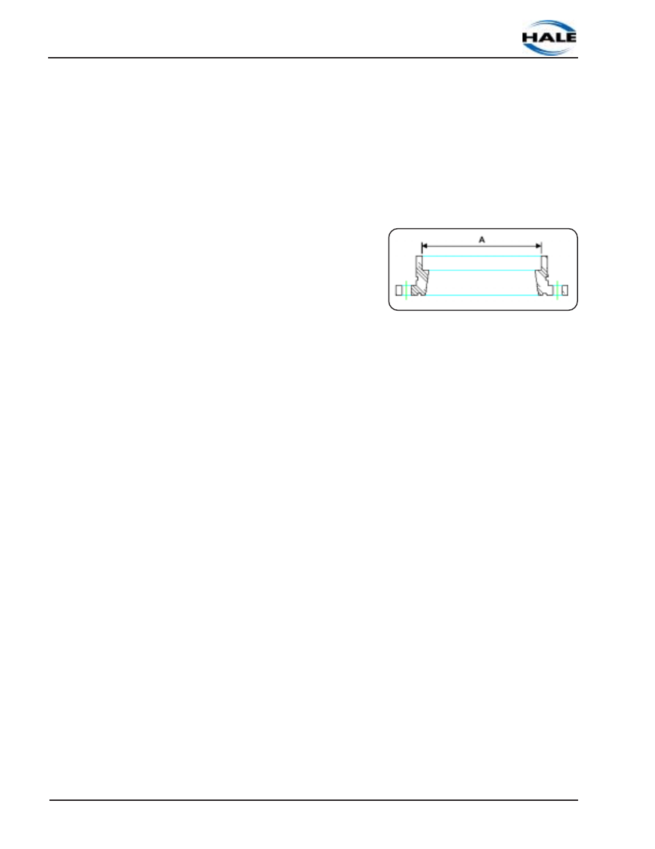
Also see Figure 6-5: “Clearance Ring Measurement.”
Inspect clearance ring ID
for signs of wear. Using a
digital caliper, measure the
inside diameter of the
clearance ring in several
places. (See A in Figure 6-
5.)
❑
New clearance ring
diameter:
7.362" to 7.366" (187.0 -187.1 mm)
❑
Wear Limit:
7.38" (187.5 mm)
If the measured dimensions do not fall within the acceptable
ranges specified, the clearance ring must be replaced.
Installation Notes
To install, follow the preceding steps in the reverse order, paying
attention to the following:
❑
Review preceding section “Before You Begin...,” beginning on
page 6-1.
❑
Pay attention to section “Cleaning and Inspection Guidelines,”
beginning on page 6-6 to ensure a thorough installation.
Impeller
See Figure 6-4: “Stainless Max Pump Breakdown” on page 6-9.
1. First, review preceding section “Before You Begin...,” beginning
on page 6-1.
2. Repeat Step 2 of preceding section “Suction Tube and Front
Clearance Ring,” beginning on page 6-9.
Figure 6-5: Clearance Ring
Measurement