4 contact assignment, Functions continued english – Bosch VMD01 M60 NTSC User Manual
Page 9
– 9 –
A1 February 03/Trb
Functions continued
English
3.4
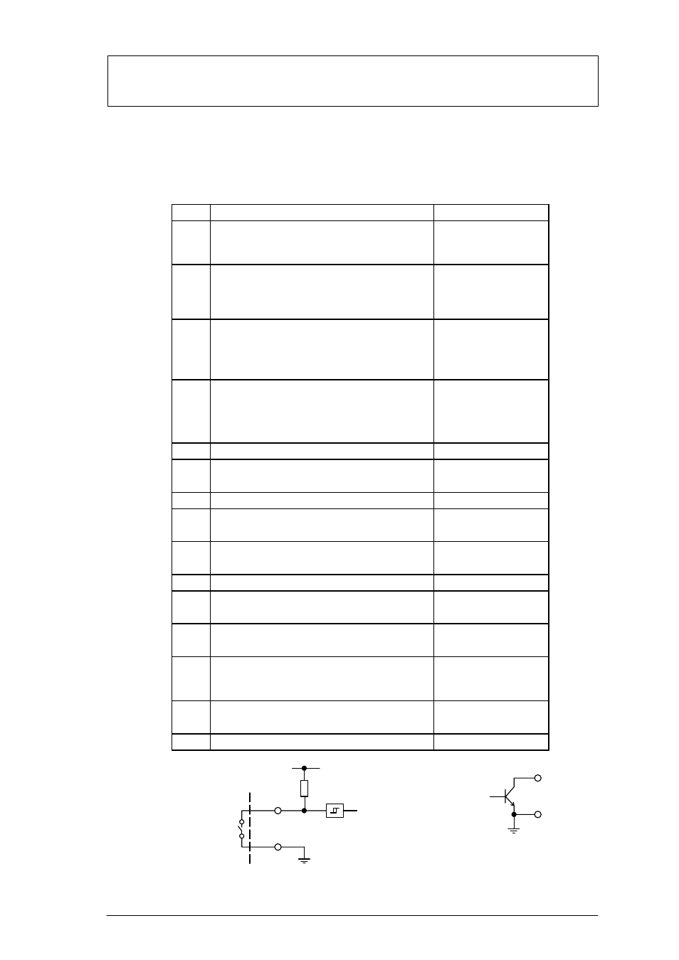
Contact assignment
PIN
1
Electrical specification
Input contact I
Open: sensor armed
At ground (Pin 5): Sensor disarmed
2
3
4
5
6
7
8
9
10
12
13
14
Output contact I
Internally switched to ground: Object detected
Open: No object detected
(constant signal, impulse or periodic impulse)
Output contact II
Internally switched to ground:
Video signal malfunction
Open: Video signal OK
Ground
Relay I
6/7 closed: Malfunction
Relay I (Middle contact)
Relay I
8/7 closed: No malfunction
Relay II
9/10 closed: No alarm
Relay II (Middle contact)
Remote control Rotary switch:
Backwards in alarm archive (–) when turned left
Remote control Rotary switch:
Forwards in alarm archive (–) when turned right
Internal pull-up
Internal pull-up
Open collector,
max. 100mA, 12V
Externally switchable
Max. 30V, max. 1A
Function
Input contact II
Open: Parameter set I active
At ground (Pin 5):
Parameter set II active
Open collector,
max. 100mA, 12V
Externally switchable
Max. 30V, max. 1A
Max. 30V, max. 1A
Max. 30V, max. 1A
Max. 30V, max. 1A
11
Relay II
11/10 closed: Alarm
Max. 30V, max. 1A
Internal pull-up
Remote control Rotary switch:
– Switchover: Live image/alarm archive
– active >2 secs. = alarm acknowledgement
Internal pull-up
Internal pull-up
15
Remote control Rotary switch: Ground
Input contacts
+5V
Output contacts
1/2
12/13/14
5/15
3/4
5/15
–
Remote control