Loading values for lintra, Mx max my max mz max fy max fz max – Norgren C/146200 LINTRA PLUS User Manual
Page 5
N/us 1.6.009.05
C/146000, C/146100, C/146200
3/10
Our policy is one of continued research and development. We therefore reserve the right to amend,
without notice, the specifications given in this document.
Theoretical forces, air consumption, cushioning length, holding forces
Cylinder
Theoretical forces lbf (N)
Air consumption ft
3
/in. (l/cm)
Cushioning length
Holding forces lbf. (N) of brake (on dry braking surface)
Ø mm
at 87 psi (6 bar)
of stroke at 87 psi (6 bar)
inches (mm)
active (L3) at 87 psi (6 bar)
passive (L4)
16
27 (120)
0.001 (0.014)
0.5 (12)
–
–
20
42 (188)
0.002 (0.022)
1 (26)
–
–
25
66 (294)
0.003 (0.035)
1 (26)
112 (5000
50 (220)
32
108 (482)
0.005 (0.056)
1.4 (35)
202 (900)
84 (375)
40
170 (754)
0.008 (0.088)
2 (50)
337 (1500)
141 (630)
50
265 (1178)
0.012 (0.137)
2.3 (60)
562 (2500)
225 (1000)
63
420 (1870)
0.02 (0.218)
2.8 (70)
899 (4000)
371 (1650)
80
678 (3016)
0.03 (0.350)
3 (75)
–
–
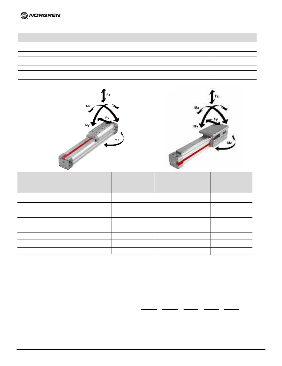
C/146000, C/146100, C/146200
Internal guide
External adjustable guide
Precision roller guide
Added caged ball linear
C/146000
C/146100
C/146200
motion guide C/146200/P
Fy
Fz
Mx
My
Mz
Fy, Fz
Mx
My, Mz
Fy
Fz
Mx
My, Mz
Fy, Fz
Mx
My, Mz
lbf.
lbf.
lbf in.
lbf in.
lbf in.
lbf.
lbf in.
lbf in.
lbf.
lbf.
lbf in.
lbf in.
lbf.
lbf in.
lbf in.
Ø mm
(N)
(N)
(Nm)
(Nm)
(Nm)
(N)
(Nm)
(Nm)
(N)
(N)
(Nm)
(Nm)
(N)
(Nm)
(Nm)
16
9
27
2.7
33.6
9.7
45
17.7
48.7
–
–
–
–
–
–
–
(40)
(120)
(0.3)
(3.8)
(1.1)
(200)
(2)
(5.5)
–
–
–
–
–
–
–
20
20
63
8.0
106.2
31.9
106
53.1
159.3
–
–
–
–
–
–
–
(90)
(280)
(0.9)
(12)
(3.6)
(470)
(6)
(18)
–
–
–
–
–
–
–
25
28
87
13.3
168.2
49.6
133
79.7
247.8
133
266
115.1
371.7
450
283
1770
(125)
(385)
(1.5)
(19)
(5.6)
(590)
(9)
(28)
(590)
(1180)
(13)
(42)
(2000)
(32)
(200)
32
37
113
26.6
292.1
88.5
176
150.5
380.6
176
351
221.3
566.5
899
566
3540
(165)
(500)
(3)
(33)
(10)
(780)
(17)
(43)
(780)
(1560)
(25)
(64)
(4000)
(64)
(400)
40
74
223
57.5
743.5
212.4
360
345.2
973.6
338
676
513.4
1416.2
899
566
3540
(330)
(990)
(6.5)
(84)
(24)
(1600)
(39)
(110)
(1500)
(3000)
(58)
(160)
(4000)
(64)
(400)
50
99
297
97.4
1062.1
309.8
450
575.3
1416.2
450
901
858.6
2124.3
1798
1593
7080
(440)
(1320)
(11)
(120)
(35)
(2000)
(65)
(160)
(2000)
(4000)
(97)
(240)
(8000)
(180)
(800)
63
155
450
177.0
2124.3
619.6
721
1062.1
3097.9
721
1441
1593.2
4602.6
1798
1593
7966
(690)
(2000)
(20)
(240)
(70)
(3200)
(120)
(350)
(3200)
(6400)
(180)
(520)
(8000)
(180)
(900)
80
176
518
239.0
3186.4
885.1
878
1593.2
4602.6
(780)
(2300)
(27)
(360)
(100)
(3900)
(180)
(520)
–
–
–
–
–
–
–
C/146200/P
The values given in the table below show the single forces in the
directions Fy and Fz and the maximum moments Mx, My and Mz.
All values are applicable only for speeds of max. 0.2 m/s.
A requirement for using these values is a constant movement (no
jerking) of the mass over the whole stroke length of the cylinder.
The reference point from which the moments for all cylinders should
be calculated is the center line of the pistons.
When a LINTRA
®
cylinder has to take several loads and moments. an
additional calculation is necessary using this formula:
Loading values for LINTRA
®
cylinders
with double carriages
Mx
+
My
+
Mz
+
Fy
+
Fz
<
_
1
Mx max
My max
Mz max
Fy max Fz max
Loading values applicable to a speed of √0.2 m/s. Maximum working life is normally reached below a speed of 1 m/s.
* The forces and moments refers to the center of the guide. They must not be exceeded in dynamic applications.