Cylinder deflection, Switches, Cushioning performance – Norgren C/146200 LINTRA PLUS User Manual
Page 4
C/146000, C/146100, C/146200
3/10
N/us 1.6.009.04
Our policy is one of continued research and development. We therefore reserve the right to amend,
without notice, the specifications given in this document.
18 (8)
2204 (1000)
lb. (kg)
inches /s
(m / s)
Ш 16
Ш 20
Ш 25
Ш 32
Ш 40
Ш 50
Ш 63
Ш 80
1763 (800)
1300 (600)
882 (400)
441 (200)
176 (80)
132 (60)
88 (40)
44 (20)
22 (10)
13 (6)
8.8 (4)
4.4 (2)
2.2 (1)
16”
(0.4)
31”
(0.8)
47”
(1.2)
63”
(1.6)
79”
(2.0)
V
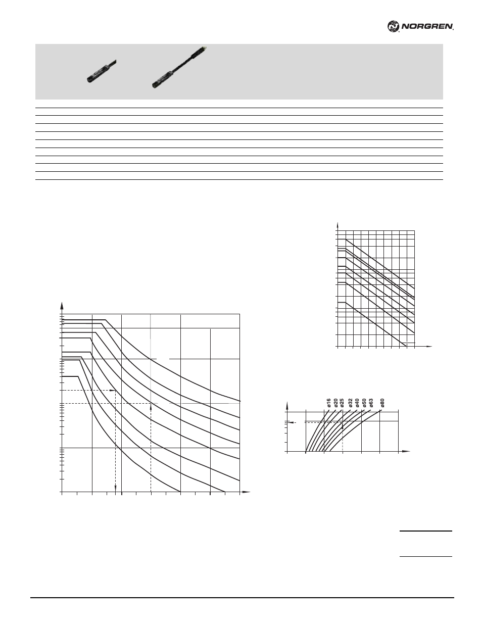
Cushioning Performance
The dynamic energy of a LINTRA
®
cylinder is caused by direct or partial external loads
which must be absorbed by pneumatic cushioning.
The cushioning ability depends to a large extent on the pneumatic circuit (e. g. counter
pressure, pre-exhaust). The values given in the diagram were tested with an operation
pressure of 87 psi (6 bar) using a 5/2 control valve. When installed horizontally, depending
upon the speed, dynamic energy can be absorbed by the cylinder. Whenever the values
given in the diagram are exceeded, the transported mass must be cushioned by additional
shock absorbers. These have to be located at the center of gravity of the mass.
inches (mm)
19.7’
(6000)
16.4’
(5000)
13’
(4000)
9.8’
(3000)
6.5’
(2000)
3.2’
(1000)
0
2
0.04” (1)
0.004” (0.1)
0.02” (0.4)
ft.
(mm)
f
0.08” (2)
0.04
(0.9)
Cylinder deflection
72”
(1830)
inches (mm)
f1= 0.04” (1 mm)
2248
(10000)
1124
(5000)
224
(1000)
112
(500)
22.5
(100)
2.25
(10)
0.22
(1)
39”
(1000)
0
6.6’
(2000)
9.8’
(3000)
13’
(4000)
16.4’
(5000)
19.6’
(6000)
Ш80
Ш63
Ш50
Ш40
Ш32
Ш25
Ш20
Ш16
Deflection due to external forces
Support length
Deflection due to cylinder weight
Example:
Cylinder Ø 32 mm, stroke length 11' (3500 mm), external load
45 lbf. (200 N) and a deflection about 0.04 (1 mm).
Maximum distance between supports = 6' (1830 mm) (see diagrams).
Therefore an additional support is required.
Support length
Example:
Cylinder Ø 40 mm. external force 40 lbf (180 N),
distance between supports 10' (3000 mm)
Required: total deflection
1. Deflection due to external force (f1)
see Diagram 1 (1mm /100 N) · 40 lbf (180 N)
2. Deflection due to cylinder weight diagram 2
Total deflection:
Max. permitted deflection (f1 + f2)
A deflection of more than 0.12" (3 mm)
is not permitted.
With cable
With connector (M8x1)
Cable
Cable with
Type
Voltage
Current
Temperature
LED
Features
Connector
Cable
connector
Reed
Solid state
V AC
V DC
max.
°F
length
type
straight
Datasheet
M/50/LSU/*V
–
10 to 240
10 to 170
180 mA
-4 to +176
•
–
8', 33'
PVC 2 x 0.25
–
N/en 4.3.005
M/50/LSU/5U
–
10 to 240
10 to 170
180 mA
-4 to +176
•
–
16'
PUR 2 x 0.25
–
N/en 4.3.005
TM/50/RAU/2S –
10 to 240
10 to 170
180 mA
-4 to +302
–
–
6.5'
Silicone 2 x 0.25 –
N/en 4.3.005
M/50/RAC/5V
–
10 to 240
10 to 170
180 mA
-4 to +176
–
Changeover
16'
PVC 3 x 0.25
–
N/en 4.3.005
M/50/LSU/CP
–
10 to 60
10 to 75
180 mA
-4 to +176
•
Plug M8x1
16'
PVC 3 x 0.25
M/P73001/5
N/en 4.3.005
–
M/50/EAP/*V
–
10 to 30
150 mA
-4 to +176
•
PNP
8', 33'
PVC 3 x 0.25
–
N/en 4.3.007
–
M/50/EAP/CP
–
10 to 30
150 mA
-4 to +176
•
PNP, plug M8x1
16'
PVC 3 x 0.25
M/P73001/5
N/en 4.3.007
–
M/50/EAP/CC
–
10 to 30
150 mA
-4 to +176
•
PNP, plug M12x1
16'
PVC 3 x 0.25
M/P34614/5
N/en 4.3.007
–
M/50/EAN/*V
–
10 to 30
150 mA
-4 to +176
•
NPN
8', 33'
PVC 3 x 0.25
–
N/en 4.3.007
–
M/50/EAN/CP
–
10 to 30
150 mA
-4 to +176
•
NPN, plug M8x1
16'
PVC 3 x 0.25
M/P73001/5
N/en 4.3.007
Switches
* Please insert cable length
0.07"(1.8 mm)
+ 0.04"(0.9 mm)
0.2" (2.7 mm)
< 0.04"(1 mm)
39"(1000 mm) Stroke