Basic application circuits, Figure 14. typical connection diagram, Cs5467 – Cirrus Logic CS5467 User Manual
Page 43
CS5467
DS714F3
43
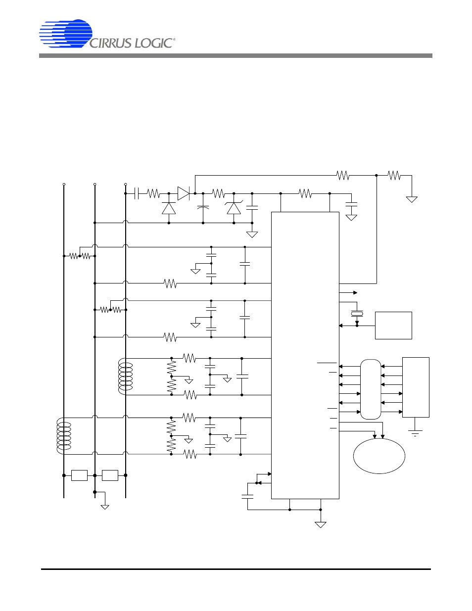
11. BASIC APPLICATION CIRCUITS
shows the CS5467 configured to measure
power in a single-phase, 3-wire system while operating
in a single-supply configuration. In this diagram, current
transformers (CT) are used to sense the line currents
and voltage dividers are used to sense the line voltages.
CS5467
R
1
R
2
9
IIN1-
10
19
20
IIN1+
PFMON
CPUCLK
XOUT
XIN
Optional
Clock
Source
Serial
Data
Interface
RESET
2
1
CS
7
SDI
27
SDO
6
SCLK
5
INT
24
E1
0.1 µF
VREFIN
12
VREFOUT
11
AGND
DGND
17
4
4.096 MHz
R
V-
IS
O
L
A
T
IO
N
(O
pt
io
na
l)
Pulse Output
Counter
26
25
C
Idiff
C
V+
C
V-
C
Vdiff
E2
IIN2-
IIN2+
R
I-
R
I+
C
Idiff
15
16
21
28
23
VIN1-
VIN1+
LOAD
CT
CT
R
I-
R
I+
LOAD
R
1
R
2
13
14
R
V-
C
V+
C
V-
C
Vdiff
VIN2-
VIN2+
VA+
VD+
0.1 µF
470 µF
500
2 uF
500
L2
10
3
0.1 µF
10 k
5 k
L1
18
N
½ R
Burden
½ R
Burden
½ R
Burden
½ R
Burden
C
I-
C
I+
C
C
C
I-
C
I+
C
C
Figure 14. Typical Connection Diagram (Single-phase, 3-wire – Direct Connect to Power Line)
- CobraNet (147 pages)
- CS4961xx (54 pages)
- CS150x (8 pages)
- CS1501 (16 pages)
- CS1601 (2 pages)
- CS1601 (16 pages)
- CS1610 (16 pages)
- CRD1610-8W (24 pages)
- CRD1611-8W (25 pages)
- CDB1610-8W (21 pages)
- CS1610A (18 pages)
- CDB1611-8W (21 pages)
- CDB1610A-8W (21 pages)
- CDB1611A-8W (21 pages)
- CRD1610A-8W (24 pages)
- CRD1611A-8W (25 pages)
- CS1615 (16 pages)
- AN403 (15 pages)
- AN401 (14 pages)
- AN400 (15 pages)
- AN375 (27 pages)
- AN376 (9 pages)
- CRD1615-8W (22 pages)
- CRD1616-8W (23 pages)
- AN402 (14 pages)
- AN404 (15 pages)
- CRD1615A-8W (21 pages)
- CS1615A (16 pages)
- CS1630 (56 pages)
- AN374 (35 pages)
- AN368 (80 pages)
- CRD1630-10W (24 pages)
- CRD1631-10W (25 pages)
- CS1680 (16 pages)
- AN405 (13 pages)
- AN379 (31 pages)
- CRD1680-7W (31 pages)
- AN335 (10 pages)
- AN334 (6 pages)
- AN312 (14 pages)
- AN Integrating CobraNet into Audio Products (16 pages)
- CobraNet Audio Routing Primer (9 pages)
- Bundle Assignments in CobraNet Systems (3 pages)
- CS2300-01 (3 pages)
- CS2000-CP (38 pages)