12 epsilon, 13 temperature measurement, 12 epsilon 6.13 temperature measurement – Cirrus Logic CS5467 User Manual
Page 22: Figure 8. sag and fault detect, Cs5467
CS5467
22
DS714F3
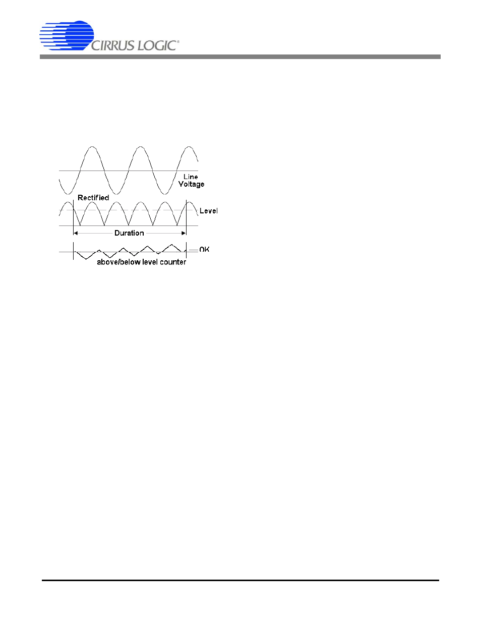
For each enabled input channel, the measured value is
rectified and compared to the associated level register.
Over the duration window, the number of samples
above and below the level are counted. If the number of
samples below the level exceeds the number of sam-
ples above, a Status register bit V1
SAG
(V2
SAG
),
I1
FAULT
(I2
FAULT
) is set, indicating a sag or fault condi-
tion. (see
6.12 Epsilon
The Epsilon register is used to set the gain of the 90°
phase shift used in the quadrature power calculation.
The value in the Epsilon register is the ratio of the line
frequency to the output word rate (OWR). It is, by de-
fault, 50/4000 (0.0125), for 50 Hz line and 4000 Hz sam-
ple (OWR) frequencies.
For 60 Hz line frequency, it is 60/4000 (0.015). Other
output word rates (OWR) can be used.
Epsilon
can also be calculated automatically by the
CS5467 by setting the AFC bit in the Mode Control
(Modes) register. The Frequency Update bit (FUP) in
the Status register is set every time the Epsilon register
has been automatically updated.
6.13 Temperature Measurement
The on-chip temperature sensor is designed to mea-
sure temperature and optionally compensate for tem-
perature drift of the voltage reference. It uses the V
BE
of
a transistor to determine temperature.
In the CS5467, voltage2 and temperature are multi-
plexed on one ADC channel. To initiate a temperature
measurement, write 1 to the Temperature Measure-
ment (T
MEAS
) register. T
MEAS
will go through counts 1,
2, 4, and back to 0. Wait for T
MEAS
to return to 0. When
done, Temperature (T) is updated. The Status register
bit TUP also indicates when the Temperature register is
updated. The Voltage2 register (V2) will not update dur-
ing the temperature measurement, but resume mea-
surement afterwards.
Temperature measurements are stored in the Temper-
ature register (T) which, by default, is configured to a
range of ±128 degrees on the Celsius (°C) scale.
The application program can change both the scale and
range of Temperature (T) by changing the Temperature
Gain (T
GAIN
) and Temperature Offset (T
OFF
) registers.
Two values must be known — the transistor’s
V
BE
per
degree, and the transistor’s V
BE
at 0 degrees. At the
time of this publication, these values are:
V
BE
(per degree) = 0.2769523 mV/°C or °K
V
BE
0 = 79.2604368 mV at 0°C
To determine the values to write to T
GAIN
and T
OFF
, use
the following formulae:
T
GAIN
= AD
FS
/
V
BE
/ T
FS
x 2
17
T
OFF
= -V
BE
0 / AD
FS
x 2
23
In the above equations, AD
FS
is the full-scale input
range of the temperature A/D converter or 833.333 mV
and T
FS
is the desired full-scale range of the Tempera-
ture (T) register. The binary exponents are the bit posi-
tions of the binary point of these registers.
To use the Celsius scale (°C) and cover the chip’s oper-
ating temperature range of -40°C to +85°C, the Temper-
ature register range needs to be ±128 degrees. T
FS
should be 128 degrees.
T
GAIN
= 833.333 / 0.2769523 / 128 x 131072
= 3081155 (0x2F03C3)
T
OFF
= -79.2604368 / 833.333 x 8388608
= -797862 (0xF3D35A)
These are the actual default values for these registers.
T
GAIN
and T
OFF
can also be used to calibrate the gain
and/or offset of the temperature sensor or A/D convert-
er. (See
To use the Kelvin (°K) scale, simply add 273 times
V
BE
/ AD
FS
x 2
23
to T
OFF
since 0°C = 273°K,. You will also
need more range. Since -40°C to +85°C is 233°K to
358°K, a T
FS
of 512 degrees should be used in the
T
GAIN
calculation.
To use the Fahrenheit (°F) scale, multiply
V
BE
by 5/9
and add 32 times the new
V
BE
/ AD
FS
x 2
23
to T
OFF
since 0°C = 32°F. You will also want to use a
T
FS
of 256
degrees to cover the -40°C to +85°C range.
Figure 8. Sag and Fault Detect