3 power offset (p1off , p2off ), Cs5467, 3 page 1 registers – Cirrus Logic CS5467 User Manual
Page 34: 1 dc offset for current (i1, And voltage (v1, 2 gain for current (i1, 3 power offset (p1, 4 ac offset for current (i1
CS5467
34
DS714F3
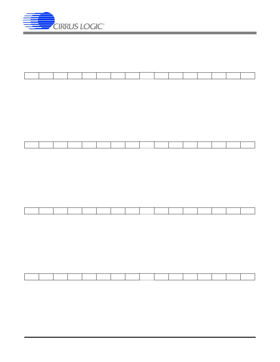
8.3 Page 1 Registers
8.3.1 DC Offset for Current (I1
OFF
, I2
OFF
) and Voltage (V1
OFF
, V2
OFF
)
Address: 0 (I1
OFF
), 2 (V1
OFF
), 7 (I2
OFF
), 9 (V2
OFF
)
Default = 0
DC offset registers I1
OFF
& V1
OFF
(I2
OFF
& V2
OFF
)
are initialized to zero on reset. During DC offset calibra-
tion, selected registers are written with the inverse of the DC offset measured. The application program can
also write the DC offset register values. These are two's complement values in the range of -1.0
value 1.0,
with the binary point to the right of the MSB.
8.3.2 Gain for Current (I1
GAIN
, I2
GAIN
) and Voltage (V1
GAIN
, V2
GAIN
)
Address: 1 (I1
GAIN
), 3 (V1
GAIN
), 8 (I2
GAIN
), 10 (V2
GAIN
)
Default = 1.0
Gain registers I1
GAIN
& V1
GAIN
(I2
GAIN
& V2
GAIN
)
are initialized to 1.0 on reset. During AC or DC gain calibra-
tion, selected register are written with the multiplicative inverse of the gain measured. These are unsigned
fixed-point values in the range of 0
value 4.0, with the binary point to the right of the second MSB.
8.3.3 Power Offset (P1
OFF
, P2
OFF
)
A
ddress: 4 (P1
OFF
), 11 (P2
OFF
)
Default = 0
Power offset P1
OFF
(P2
OFF
) is added to instantaneous power and averaged over a low-rate interval to yield
P1
AVG
(P2
AVG
) register results. It can be used to reduce systematic energy errors. These are two's comple-
ment values in the range of -1.0
value 1.0, with the binary point to the right of the MSB.
8.3.4 AC Offset for Current (I1
ACOFF
, I2
ACOFF
) and Voltage (V1
ACOFF
, V2
ACOFF
)
Address: 5 (I1
ACOFF
), 6 (V1
ACOFF
), 12 (I2
ACOFF
), 13 (V2
ACOFF
)
Default = 0
AC offset registers I1
ACOFF
& V1
ACOFF
(
V
ACOFF
&
V2
ACOFF
)
are initialized to zero on reset. These are added
to the RMS results before being stored to the RMS result registers. They can be used to reduce systematic
errors in the RMS results. These are two's complement values in the range of -1.0
value 1.0, with the bi-
nary point to the right of the MSB.
MSB
LSB
-(2
0
)
2
-1
2
-2
2
-3
2
-4
2
-5
2
-6
2
-7
.....
2
-17
2
-18
2
-19
2
-20
2
-21
2
-22
2
-23
MSB
LSB
2
1
2
0
2
-1
2
-2
2
-3
2
-4
2
-5
2
-6
.....
2
-16
2
-17
2
-18
2
-19
2
-20
2
-21
2
-22
MSB
LSB
-(2
0
)
2
-1
2
-2
2
-3
2
-4
2
-5
2
-6
2
-7
.....
2
-17
2
-18
2
-19
2
-20
2
-21
2
-22
2
-23
MSB
LSB
-(2
0
)
2
-1
2
-2
2
-3
2
-4
2
-5
2
-6
2
-7
.....
2
-17
2
-18
2
-19
2
-20
2
-21
2
-22
2
-23