Figure 24. power configuration register pwrcfg, Cs5374 – Cirrus Logic CS5374 User Manual
Page 39
CS5374
CS5374
39
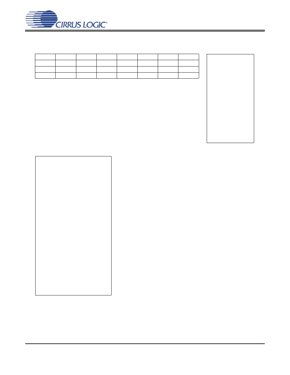
(MSB)7
6
5
4
3
2
1
(LSB)0
adc_lpwr
---
amp_i1_1
amp_i1_0
rough
i1_tail
amp_i5_1
amp_i5_0
R/W
R/W
R/W
R/W
R/W
R/W
R/W
R/W
0
0
0
0
0
0
0
0
Figure 24. Power Configuration Register PWRCFG
Bit definitions:
7
adc_lpwr
Modulator Bias
1: reduced current
0: nominal current
6
---
reserved
5:4
amp_i1
Amplifier i1 Bias
11: 2/3
10: 1/3
01: 4/3
00: nominal current
3
rough
Modulator Rough Phase
1: reduced current
0: nominal current
2
i1_tail
Amplifier i1 Tail Current
1: reduced current
0: nominal current
1:0
amp_i5
Amplifier i5 Bias
11: 7/11
10: 9/13
01: 15/13
00: nominal current
Address: 0x04
---
Not defined
(read as 0)
R
Readable
W
Writable
R/W
Readable
and Writable
Bits in bottom rows
are reset condition.
Reset Condition : 0000_0000 (0x00) : Default value
Normal Operation : 1000_1111 (0x8F) : Reduced power
Power Down Operation : 0000_0000 (0x00) : Default value
- CobraNet (147 pages)
- CS4961xx (54 pages)
- CS150x (8 pages)
- CS1601 (2 pages)
- CS1501 (16 pages)
- CS1601 (16 pages)
- CS1610 (16 pages)
- CRD1610-8W (24 pages)
- CRD1611-8W (25 pages)
- CDB1610-8W (21 pages)
- CS1610A (18 pages)
- CDB1611-8W (21 pages)
- CDB1610A-8W (21 pages)
- CDB1611A-8W (21 pages)
- CRD1610A-8W (24 pages)
- CRD1611A-8W (25 pages)
- CS1615 (16 pages)
- AN403 (15 pages)
- AN401 (14 pages)
- AN400 (15 pages)
- AN375 (27 pages)
- AN376 (9 pages)
- CRD1615-8W (22 pages)
- CRD1616-8W (23 pages)
- AN402 (14 pages)
- AN404 (15 pages)
- CRD1615A-8W (21 pages)
- CS1615A (16 pages)
- CS1630 (56 pages)
- AN374 (35 pages)
- AN368 (80 pages)
- CRD1630-10W (24 pages)
- CRD1631-10W (25 pages)
- CS1680 (16 pages)
- AN405 (13 pages)
- AN379 (31 pages)
- CRD1680-7W (31 pages)
- AN335 (10 pages)
- AN334 (6 pages)
- AN312 (14 pages)
- AN Integrating CobraNet into Audio Products (16 pages)
- CobraNet Audio Routing Primer (9 pages)
- Bundle Assignments in CobraNet Systems (3 pages)
- CS2300-01 (3 pages)
- CS2000-CP (38 pages)