Modulator operation, 1 modulator anti-alias filter, Modulator anti-alias filter – Cirrus Logic CS5374 User Manual
Page 18: Figure 14. cs5374 modulator block diagram, Cs5374
CS5374
CS5374
18
4.
MODULATOR OPERATION
The CS5374 modulators are fourth-order
ΔΣ type
optimized for extremely high-resolution measure-
ment of signals between DC and 2000 Hz. When
combined with the internal differential amplifiers,
the CS4373A test DAC and CS5376A digital filter,
a small, low-power, self-testing, high-accuracy,
multi-channel measurement system results.
The modulators have high dynamic range and low
total harmonic distortion with very low power con-
sumption. They are optimized for extremely high-
resolution measurement of 5 V
p-p
or smaller differ-
ential signals. They convert analog input signals
from the differential amplifiers to an oversampled
serial bit stream which is then passed to the digital
filter.
The companion CS5376A digital filter generates
the clock and synchronization inputs for the modu-
lators while receiving the one-bit data and over-
range flag outputs. The digital filter decimates the
modulator’s oversampled output bit stream to a
high-resolution, 24-bit output at the final selected
output word rate.
4.1 Modulator Anti-Alias Filter
The modulator inputs are required to be bandwidth
limited to ensure modulator loop stability and pre-
vent high-frequency signals from aliasing into the
measurement bandwidth. The use of simple, sin-
gle-pole, differential, low-pass RC filters across
the INR± and INF± inputs ensures high-frequency
signals are rejected before they can alias into the
measurement bandwidth.
The approximate –3 dB corner of the input anti-
alias filter is nominally set to the internal analog
sampling rate divided by 64, which itself is a divi-
sion by 4 of the MCLK rate.
Figure 1 on page 6 illustrates the CS5374 amplifi-
er-to-modulator analog connections with input
anti-alias filter components. Filter components on
the rough and fine pins should be identical values
for optimum performance, with the capacitor val-
ues a minimum of 0.02
μF. The rough input can use
either X7R or C0G-type capacitors, while the fine
input requires C0G-type capacitors for optimal lin-
earity. Using X7R-type capacitors on the fine ana-
log inputs will significantly degrade total harmonic
distortion performance.
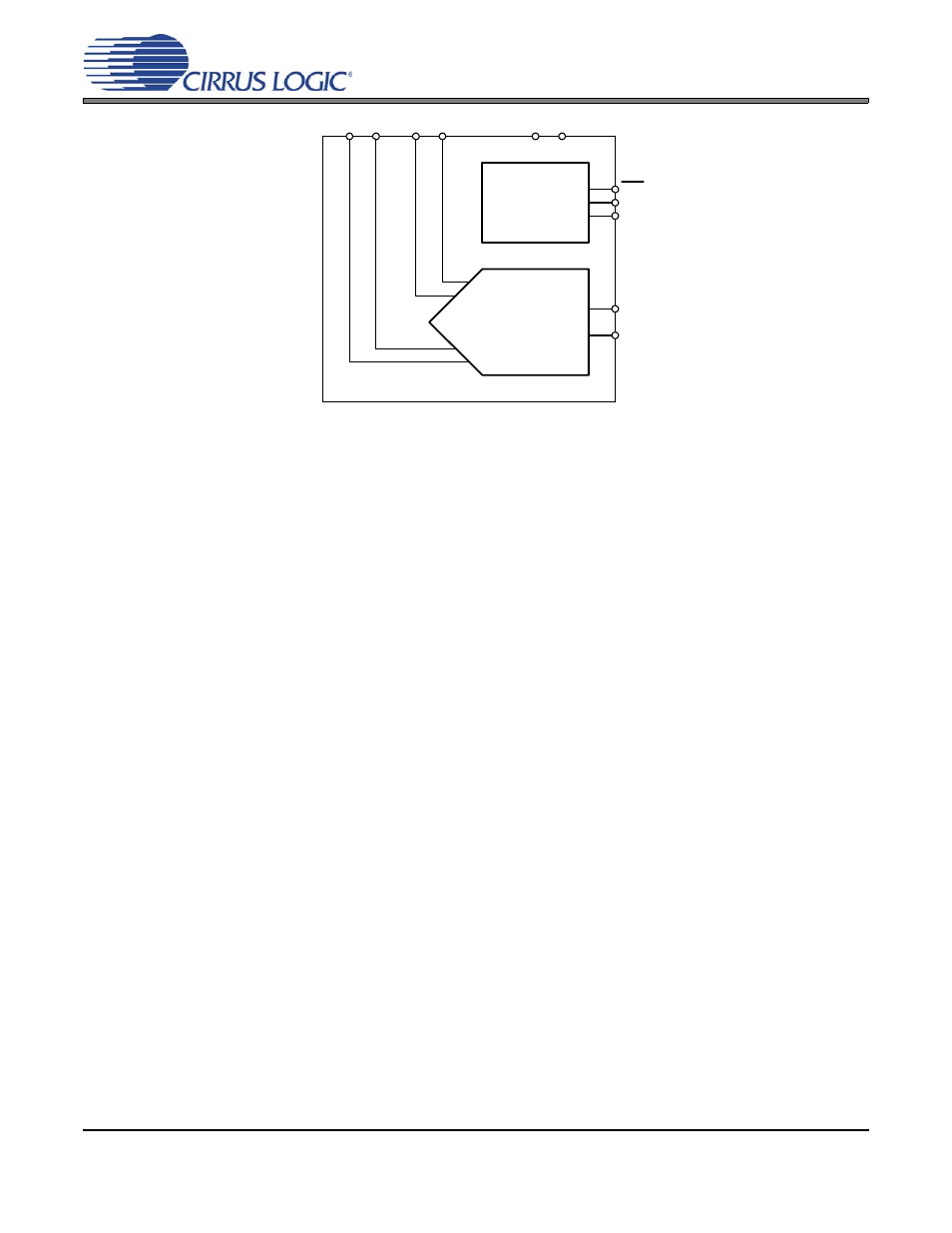
Reset, Clock,
and
Synchronization
INR1-
VREF-
MFLAG1
MCLK
MSYNC
4
th
Order
Modulator
INF1- INF1+INR1+
RST
VREF+
MDATA1
Figure 14. CS5374 Modulator Block Diagram
•
MCLK Frequency = 2.048 MHz
•
Sampling Frequency = MCLK / 4 = 512 kHz
•
–3 dB Filter Corner = Sampling Freq / 64 = 8 kHz
•
RC filter = 1 / [ 2
π x (2 x R
series
) x C
diff
] ~ 8 kHz