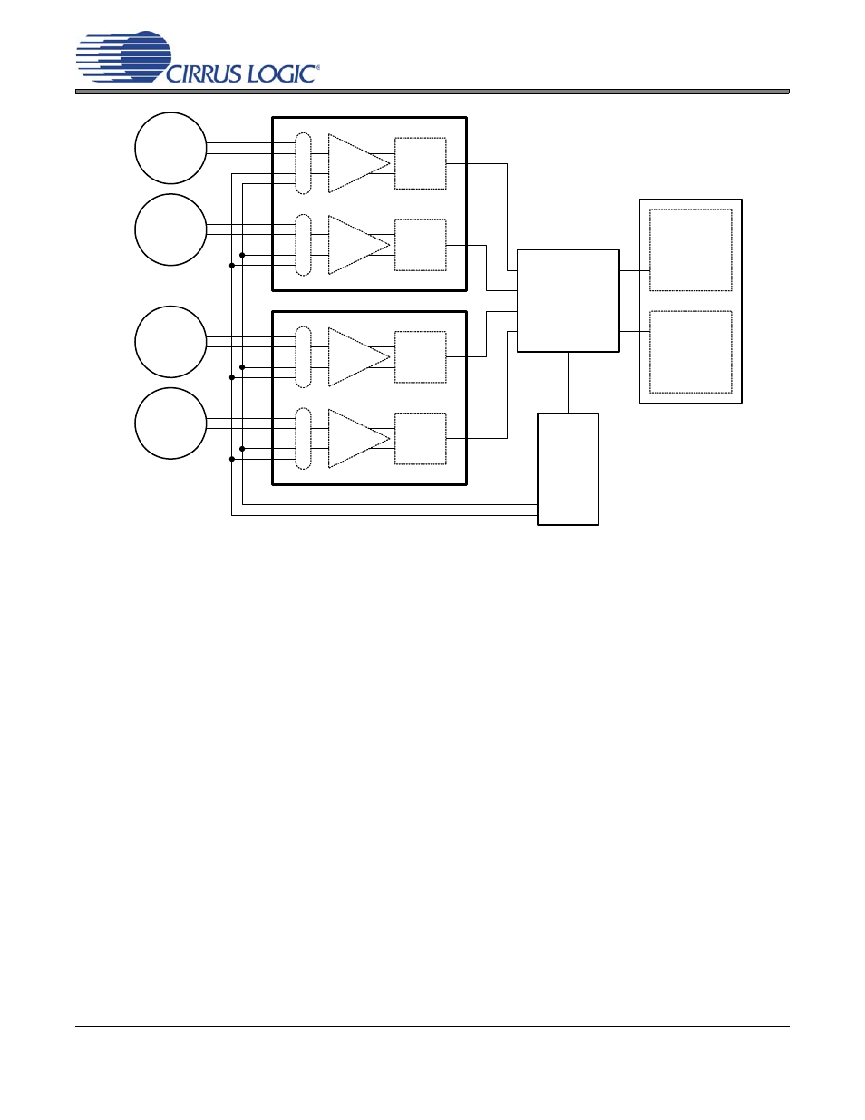
General description, Figure 10. cs5374 system block diagram, Cs5374 – Cirrus Logic CS5374 User Manual
Page 14
CS5374
CS5374
14
2.
GENERAL DESCRIPTION
The CS5374 combines two marine seismic analog
measurement channels into one 7 mm x 7 mm QFN
package. Each measurement channel consists of a
high input impedance programmable gain differen-
tial amplifier that buffers analog signals into a
high-performance, fourth-order
ΔΣ modulator. The
low-noise
ΔΣ modulator converts the analog signal
into a one-bit serial bit stream suitable for the
CS5376A digital filter.
Each amplifier has two sets of external inputs, INA
and INB, to simplify system design as inputs from
a hydrophone sensor or the CS4373A test DAC. An
internal 800
Ω termination can also be selected for
noise tests. Gain settings are binary weighted (1x,
2x, 4x, 8x, 16x, 32x, 64x) and match the CS4373A
test DAC output attenuation settings for full-scale
testing at all gain ranges. Both the input multiplex-
er and gain are set by registers accessed through a
standard SPI™ port.
Each fourth-order
ΔΣ modulator has very high dy-
namic range combined with low total harmonic dis-
tortion and low power consumption. It converts
differential analog signals from the amplifier to an
oversampled
ΔΣ serial bit stream which is decimat-
ed by the CS5376A digital filter to a 24-bit output
at the final output word rate.
shows the system-level architecture of a
4-channel acquisition system using two CS5374,
one CS5376A digital filter and one CS4373A test
DAC.
shows connection dia-
grams for the CS5374 device when connected to
the CS5376A digital filter
.
Hydrophone
Sensor
Hydrophone
Sensor
Hydrophone
Sensor
Hydrophone
Sensor
DS
Modulator
Digital Filter
CS5376A
Test
DAC
Microcontroller
or
Configuration
EEPROM
System
Telemetry
AMP
CS4373A
CS5374
DS
Modulator
AMP
M
U
X
DS
Modulator
AMP
M
U
X
CS5374
DS
Modulator
AMP
M
U
X
M
U
X
Figure 10. CS5374 System Block Diagram