3 cs1810xx/cs4961xx package, Figure 31. 144-pin lqfp package drawing – Cirrus Logic CS1810xx User Manual
Page 51
CobraNet Hardware User’s Manual
Mechanical Drawings and Schematics
DS651UM23
©
Copyright 2005 Cirrus Logic, Inc.
51
Version 2.3
9.3
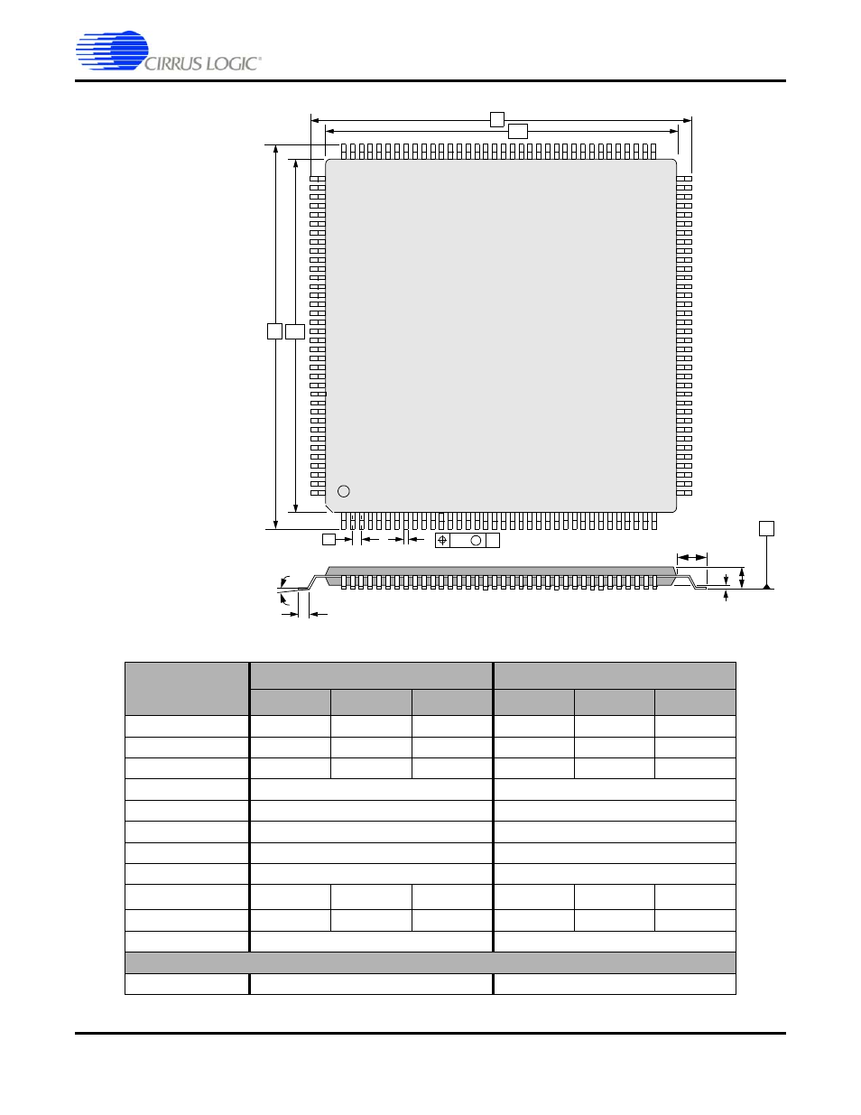
CS1810xx/CS4961xx Package
DIM
MILLIMETERS
INCHES
MIN
NOM
MAX
MIN
NOM
MAX
A
---
---
1.60
---
---
.063”
A1
0.05
---
0.15
.002”
---
.006”
b
0.17
0.22
0.27
.007”
.009”
.011”
D
22.00 BSC
.866”
D1
20.00 BSC
.787”
E
22.00 BSC
.866”
E1
20.00 BSC
.787”
e
0.50 BSC
.020”
θ
0°
---
7°
0°
---
7°
L
0.45
0.60
0.75
.018”
.024”
.030”
L1
1.00 REF
.039” REF
TOLERANCES OF FORM AND POSITION
ddd
0.08
.003”
D1
D
e
L
θ
b
A1
A
Figure 31. 144-Pin LQFP Package Drawing
L1
Notes:
1. Controlling dimension is millimeter.
2. Dimensioning and tolerancing per ASME
Y14.5M-1994.
E1
E
M
B
SEATING PLANE
ddd
B
This manual is related to the following products: