Figure 20. general pcb dimensions, Not to scale – Cirrus Logic CS1810xx User Manual
Page 40
40
©
Copyright 2005 Cirrus Logic, Inc.
DS651UM23
Version 2.3
CobraNet Hardware User’s Manual
Mechanical Drawings and Schematics
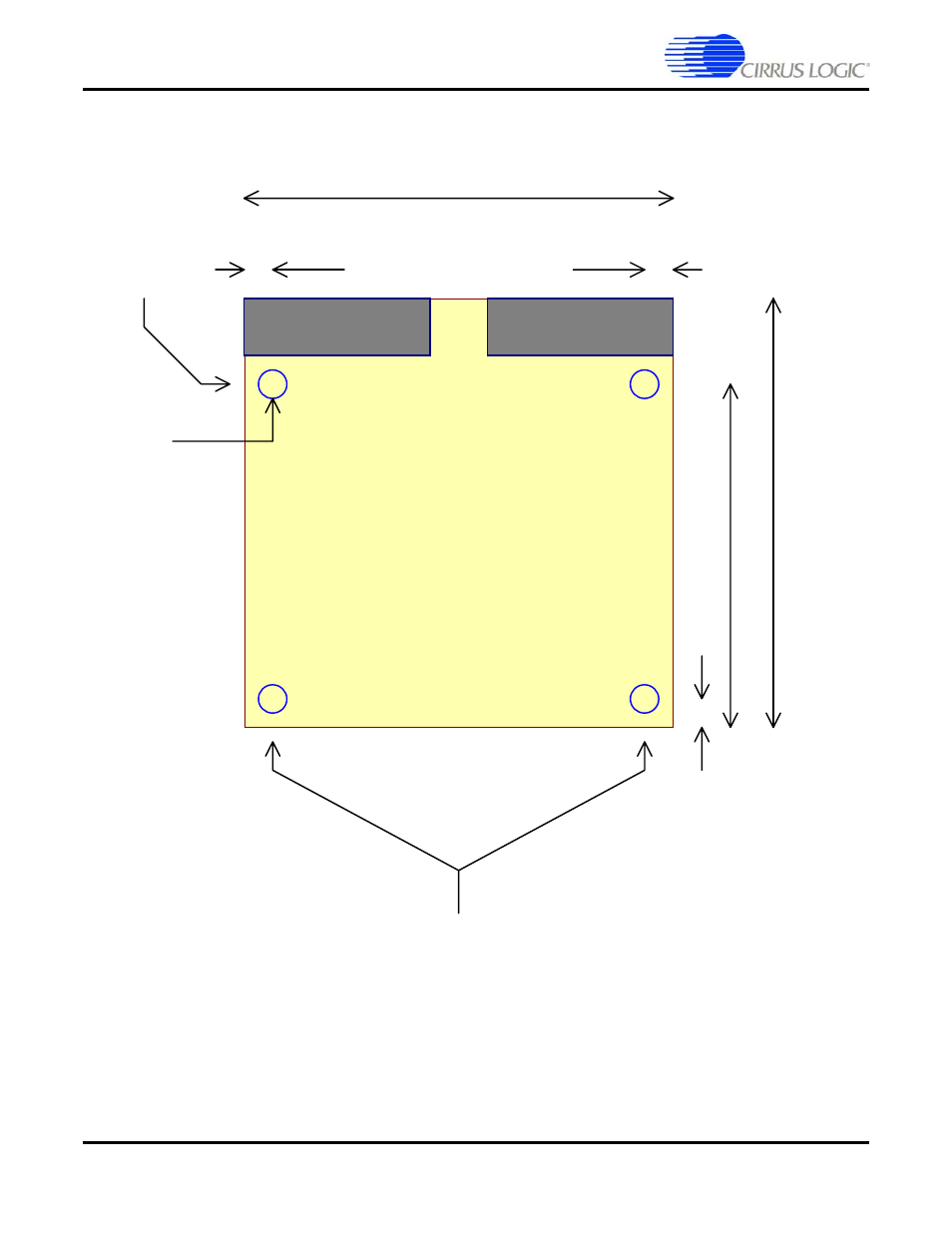
Figure 20. General PCB Dimensions
3.
500
3.500
4x 0.
16 Ho
le
, 0.
3 pads
2x M
o
unting
ho
le
s f
o
r f
ro
n
t f
ace
pl
ate
.
2x M
o
unting
ho
le
s f
o
r PCB
stando
ff
s
0.
3
0.175
2.
86
0.175
Ge
ne
ra
l PCB di
m
ens
io
ns
Co
m
p
o
n
en
t Side
=
J
1
Co
m
p
o
n
en
t Side
=
J
3
B
o
tto
m
Side
=
J
2
B
o
tto
m
Side
=
J
4
A1
A1
B1
B1
A20
B20
A20
B20
V
ie
w
ed
fr
o
m
c
o
m
p
o
n
en
t s
id
e u
p
.
NOT TO SCALE
This manual is related to the following products:
See also other documents in the category Cirrus Logic Hardware:
- CobraNet (147 pages)
- CS150x (8 pages)
- CS1501 (16 pages)
- CS1601 (2 pages)
- CS1601 (16 pages)
- CS1610 (16 pages)
- CRD1610-8W (24 pages)
- CRD1611-8W (25 pages)
- CDB1610-8W (21 pages)
- CS1610A (18 pages)
- CDB1611-8W (21 pages)
- CDB1610A-8W (21 pages)
- CDB1611A-8W (21 pages)
- CRD1610A-8W (24 pages)
- CRD1611A-8W (25 pages)
- CS1615 (16 pages)
- AN403 (15 pages)
- AN401 (14 pages)
- AN400 (15 pages)
- AN375 (27 pages)
- AN376 (9 pages)
- CRD1615-8W (22 pages)
- CRD1616-8W (23 pages)
- AN402 (14 pages)
- AN404 (15 pages)
- CRD1615A-8W (21 pages)
- CS1615A (16 pages)
- CS1630 (56 pages)
- AN374 (35 pages)
- AN368 (80 pages)
- CRD1630-10W (24 pages)
- CRD1631-10W (25 pages)
- CS1680 (16 pages)
- AN405 (13 pages)
- AN379 (31 pages)
- CRD1680-7W (31 pages)
- AN335 (10 pages)
- AN334 (6 pages)
- AN312 (14 pages)
- AN Integrating CobraNet into Audio Products (16 pages)
- CobraNet Audio Routing Primer (9 pages)
- Bundle Assignments in CobraNet Systems (3 pages)
- CS2300-01 (3 pages)
- CS2000-CP (38 pages)