Figure 22. faceplate dimensions, Not to scale – Cirrus Logic CS1810xx User Manual
Page 42
42
©
Copyright 2005 Cirrus Logic, Inc.
DS651UM23
Version 2.3
CobraNet Hardware User’s Manual
Mechanical Drawings and Schematics
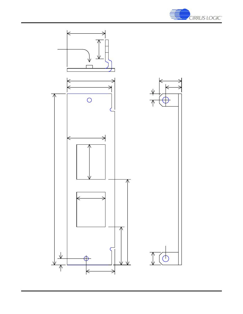
Figure 22. Faceplate Dimensions
F
ace
pl
ate
m
ate
rial
is 20 g
u
ag
e,
0.
037"
thick
0.
300
0.340
0.490
2x,
Ho
le
Diam
et
er
0.
160
3.
500
0.
300
1.000
0.862
1.000 max, 0.9 typ.
0.
125 dia,
2x
0.500
4-40 PEM
's,
x2
0.800
1.
343
0.
431
0.550
0.
680
F
a
ce
p
late
D
im
en
sion
s
Chro
m
e pl
ating
o
n
f
ace
pl
ate
0.
175
0.
175
0.810
1.
333
0.
421
0.
700
N
ot
e:
M
echani
cal
di
m
ensi
ons f
o
r t
h
e C
M
-2 and C
M
-1 R
ev F are i
d
ent
ical
.
T
h
ere are di
ff
erences w
it
h
earl
ie
r versi
ons of
t
h
e C
M
-1, how
ever. For
ref
erence, earlier versions of
the
C
M
-1 dim
ensions are show
n in R
E
D
.
NOT TO SCALE
This manual is related to the following products: