2 signal descriptions, 1 host port signals, 2 asynchronous serial port (uart bridge) signals – Cirrus Logic CS1810xx User Manual
Page 12
12
©
Copyright 2005 Cirrus Logic, Inc.
DS651UM23
Version 2.3
CobraNet Hardware User’s Manual
Pinout and Signal Descriptions
4.2
Signal Descriptions
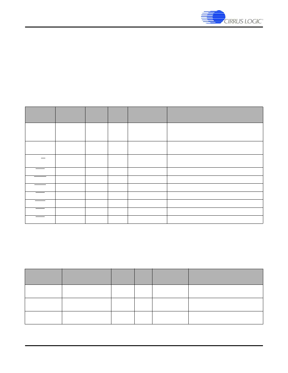
4.2.1 Host Port Signals
The host port is used to manage and monitor the CobraNet interface. Electrical operation
and protocol is detailed in the
"Host Management Interface (HMI)" on page 23
Manual.
The host port can operate in two modes in order to accomodate Motorola
®
or Intel
®
style
interfaces. The default mode is Motorola. Intel mode is set via a firmware modification.
4.2.2 Asynchronous Serial Port (UART Bridge) Signals
Level-shifting drive circuits are typically required between these signals and any external
connections.
Table 2-1: Host Port Signals
Signal
Description
Direction
CM-2
Pin #
CS1810xx/
CS4961xx Pin #
Notes
HDATA[7:0] Host
Data
In/Out
J1:A19,
A[17:11]
111, 112, 114,
115, 117, 118,
102, 121
Host port data.
HADDR[3:0] Host
Address
In
J1:A20,
A[10:8]
105, 106, 109,110 Host port address.
HRW
Host
Direction
In
J1:A4
107
Host port transfer direction (Motorola mode).
HRD
Host Read
In
J1:A4
107
Host Read (Intel mode).
HREQ
Host Request
Out
J1:A6
140
Host port data request.
HACK
Host Alert
Out
J1:A3
102
Host port interrupt request.
HDS
Host Strobe
In
J1:A5
103
Host port strobe (Motorola mode).
HWR
Host Write
In
J1:A5
103
Host Write (Intel mode).
HEN
Host Enable
In
J1:A7
104
Host Port Enable.
HCS
Select
In
J1:A7 104
Select
(Intel
mode).
Signal
Description
Direction
CM-2
Pin #
CS1810xx/
CS4961xx Pin #
Notes
UART_RXD
Asynchronous Serial
Receive Data
In
J1:A1
26
Pull-up to VCC if unused.
UART_TXD
Asynchronous Serial
Transmit Data
Out
J1:B1 25
UART_TX_OE
Transmit Drive Enable
Out
J1:A2
23
Enable transmit (active high) drive for
two wire multi-drop interface.