5 miscellaneous signals, 6 power and ground signals – Cirrus Logic CS1810xx User Manual
Page 14
14
©
Copyright 2005 Cirrus Logic, Inc.
DS651UM23
Version 2.3
CobraNet Hardware User’s Manual
Pinout and Signal Descriptions
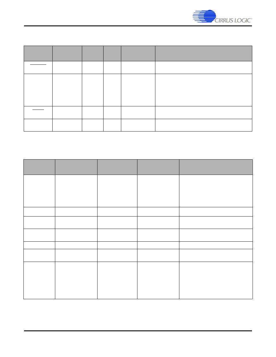
4.2.5 Miscellaneous Signals
4.2.6 Power and Ground Signals
Signal
Description
Direction
CM-2
Pin #
CS1810xx/
CS4961xx Pin #
Notes
HRESET
Reset
In
J1:A18 93
System reset (active low).
10 ns max rise time. 1 ms min assertion time.
WATCHDOG
Watch Dog
Out
J3:A17
95
Toggles at 750 Hz nominal rate to indicate proper
operation. Period duration in excess of 200 ms
indicates hardware or software failure has occurred
and the interface should be reset. Note that
improper operation can also be indicated by short
pulses (<100 ns).
MUTE
Interface
Ready
Out
J3:A2
92
Asserts (active low) during initialization and when a
fault is detected or connection to the network is lost.
NC
No Connect
-
-
28, 50-53, 78-
81, 141, 142
Signal
Description
CM-2 Pin #
CS1810xx/CS4961xx
Pin #
Specification
VCC
_+
3V
System Digital +3.3 v
J1:B20, B17, B15,
B13, B11, B9, B7,
B5, B3
J3:B14, B12, B10,
B8, B6, B4, B2
N/A
3.3
±
0.3v, 500 mA Typ., 750 mA Max.
VCC
_+
5V
J3;B[18:17] N/A
Backwards Compatibility
VDDD N/A
10, 24, 54, 66, 83,
98, 119, 130
+1.8 V @ 500mA Typ. for Core Logic
VDDIO N/A
18, 33, 44, 60, 73,
91, 113, 136
+3.3 V @ 120mA Typ. for I/O Logic
VDDA
N/A
129
Filtered +1.8 V @ 10mA Typ.
AUX_POWER
[3-0]
J3:B[20:19],
A[20:19]
N/A
GND
Digital Ground
J1:B19, B16, B14,
B12, B10, B8, B6,
B4, B2
J3:B16, B15, B13,
B11, B9, B7, B5,
B3, B1
13, 21, 27, 36, 47,
57, 63, 69, 76, 86,
94, 101, 116, 122,
126, 133, 139