0 digital audio interface, Cs18100x/cs49610x & cs18101x/cs49611x, Cs18102x/cs49612x – Cirrus Logic CS1810xx User Manual
Page 19: Ibed in
CobraNet Hardware User’s Manual
Digital Audio Interface
DS651UM23
©
Copyright 2005 Cirrus Logic, Inc.
19
Version 2.3
6.0 Digital Audio Interface
The CS18101x/CS49611x, CS18102x/CS49612x, and CM-2 support four bi-directional
synchronous serial interfaces. The CS18100x & CS49610x support one bi-directional
synchronous serial interface. All interfaces operate in master mode with DAO1_SCLK as
the bit clock and FS1 as the frame clock. A sample period worth of synchronous serial
data includes two (or four) audio channels. CobraNet supports two synchronous serial bit
rates: 48 Khz and 96 KHz. However, 96 kHz sample rate is not available when using
CS18102x/CS49612x with 16X16 channels. Bit rate is selected by the
modeRateControl
variable. All synchronous serial interfaces operate from a common clock at the same bit
rate.
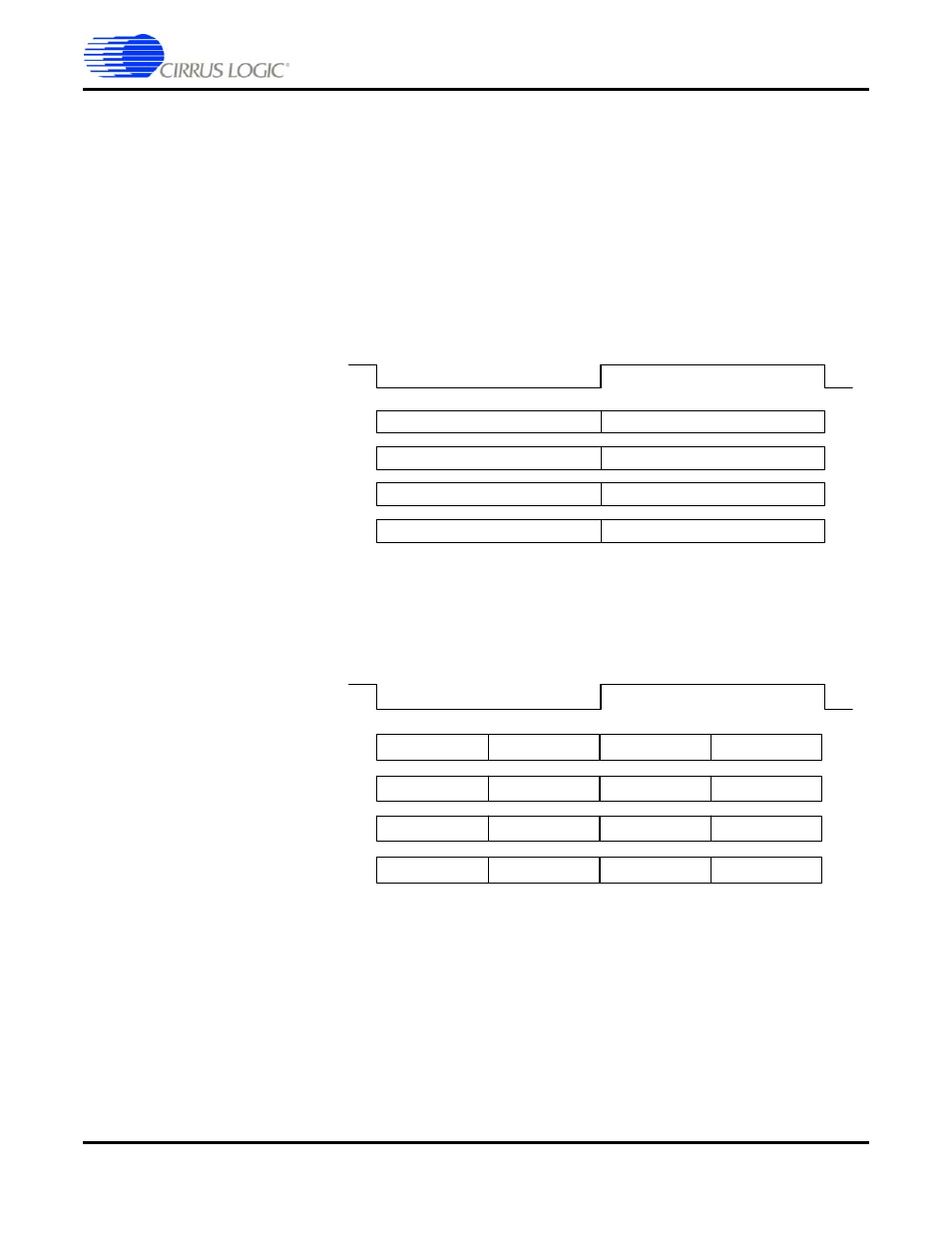
Figure 4. Channel Structure for Synchronous Serial Audio at 64FS (One Sample Period) - CS18100x/CS49610x &
CS18101x/CS49611x
Figure 5. Channel Structure for Synchronous Serial Audio at 128FS (One Sample Period) - CS18102x/CS49612x
Default channel ordering is shown above. Note that the first channel always begins after
the rising or falling edge of FS1 (depending on the mode).
DAI1_SCLK period depends on the sample rate selected. Up to 32 significant bits are
received and buffered by the DSP for synchronous inputs. Up to 32 significant bits are
transmitted by the DSP for synchronous outputs. Bit 31 is always the most significant
(sign) bit. A 16-bit audio source must drive to bit periods 31-16 with audio data and bits
15-0 should be actively driven with either a dither signal or zeros. Cirrus Logic
recommends driving unused LS bits to zero.
1
2
F S 1
D A O 1 _ D A T A 0 / D A I1 _ D A T A 0
3
4
5
6
7
8
*D A O 1 _ D A T A 1 / D A I1 _ D A T A 1
*D A O 1 _ D A T A 2 / D A I1 _ D A T A 2
*D A O 1 _ D A T A 3 / D A I1 _ D A T A 3
* N o t p re s e n t in C S 1 8 1 0 0 x o r C S 4 9 6 1 0 x .
1
2
FS1
DAO1_DATA0 / DAI1_DATA0
5
6
9
10
13
14
DAO1_DATA1 / DAI1_DATA1
DAO1_DATA2 / DAI1_DATA2
DAO1_DATA3 / DAI1_DATA3
3
4
7
8
11
12
15
16