WIKA D-21-9 User Manual
Page 36
D-20-9 / D-21-9
GB
WIKA Additional Instructions Pressure Transmitter with CANopen Interface D-20-9 / D-21-9
36
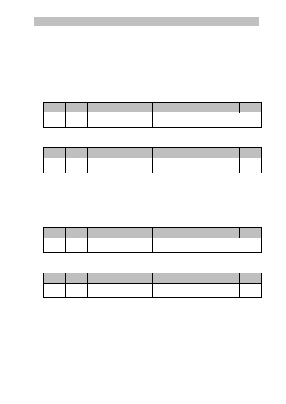
Example 1:
Pressure Range: -1 … 2.5 bar (=> -100,000 … 250,000 Pa output value)
Calibration Point 1:
Pressure applied (reference value): -0.9 bar
The user writes the value that the device is supposed to indicate under the pressure currently applied to object
6121h subindex 1 (AI_Input_Scaling_1_PV), i.e. in this example -90,000 Pa (=> FF FE A0 70 h)
ID
DLC
Byte0
Byte1
Byte2
Byte3
Byte4
Byte5
Byte6
Byte7
21h
61h
70h
A0h
FEh
FFh
600h
+
Node-ID
8
CS =
22h
Index 6121h
01h
Subindex
desired value (as integer32)
The pressure transmitter confirms the successful service by:
ID
DLC
Byte0
Byte1
Byte2
Byte3
Byte4
Byte5
Byte6
Byte7
21h
61h
580h
+
Node-ID
8
CS =
60h
Index 6121h
01h
Subindex
00h
00h
00h
00h
Calibration Point 2:
Pressure applied (reference value): 2.5 bar
The user writes the value that the device is supposed to indicate under the pressure currently applied to object
6123h subindex 1 (AI_Input_Scaling_2_PV), i.e. in this example 250,000 Pa (=> 00 03 D0 90 h)
ID
DLC
Byte0
Byte1
Byte2
Byte3
Byte4
Byte5
Byte6
Byte7
23h
61h
90h
D0h
03h
00h
600h
+
Node-ID
8
CS =
22h
Index 6121h
01h
Subindex
desired value (as integer32)
The pressure transmitter confirms the successful service by:
ID
DLC
Byte0
Byte1
Byte2
Byte3
Byte4
Byte5
Byte6
Byte7
23h
61h
580h
+
Node-ID
8
CS =
60h
Index 6121h
01h
Subindex
00h
00h
00h
00h