1 wiring the tp rj45 connectors, Wiring the tp rj-45 connectors, Figure 32: tp pinout wiring – Kramer Electronics VP-8x8TP User Manual
Page 38
KRAMER: SIMPLE CREATIVE TECHNOLOGY
Firmware Upgrade
34
11.1
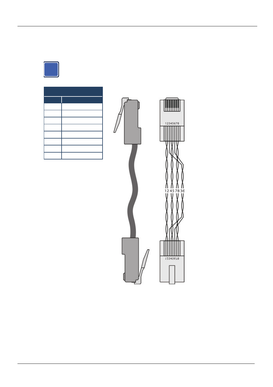
Wiring the TP RJ-45 Connectors
This section defines the TP pinout, using a straight pin-to-pin cable with RJ-45
connectors.
i
Note, that the cable Ground shielding must be connected / soldered to
the connector shield.
EIA /TIA 568B
Figure 32: TP Pinout Wiring
PIN
Wire Color
1
Orange / White
2
Orange
3
Green / White
4
Blue
5
Blue / White
6
Green
7
Brown / White
8
Brown
See also other documents in the category Kramer Electronics Routers:
- VM-28H (23 pages)
- VM-216H (25 pages)
- VM-22H (12 pages)
- VM-24H (23 pages)
- VM-24HC (21 pages)
- VM-24HD (10 pages)
- VM-24HDCP (19 pages)
- VM-42 (8 pages)
- VP-222K (10 pages)
- VP-242 (8 pages)
- VP-32K (13 pages)
- VS-202YC (23 pages)
- 4x1S (15 pages)
- 4x1V (12 pages)
- 6241HDxl (10 pages)
- 6241N (10 pages)
- 6502 (12 pages)
- PT-201VGA (8 pages)
- TailorMade (21 pages)
- TailorMade (22 pages)
- VP-1201 (50 pages)
- VP-12x8 (34 pages)
- VP-1608 (46 pages)
- VS-88SDI (42 pages)
- VP-321xl (37 pages)
- VP-16x18AK (60 pages)
- VP-201xl (8 pages)
- VP-211K (15 pages)
- VP-27 (32 pages)
- VS-66HN (25 pages)
- VS-88HDxl (43 pages)
- VP-28 (42 pages)
- VP-2x2 (17 pages)
- VP-31 (25 pages)
- VP-311DVI (20 pages)
- VS-88HD (21 pages)
- VS-88HD (44 pages)
- VP-81KSi (51 pages)
- VP-31KSi (16 pages)
- VP-31KSi (48 pages)
- VP-41 (8 pages)
- VP-411DS (22 pages)
- VS-81HDxl (25 pages)
- VP-4x1CS (39 pages)
- VP-4x4K (61 pages)