Table 2: vp-8x8tp front and rear panel features, Table 2, 7table 2: vp-8x8tp front and rear panel features – Kramer Electronics VP-8x8TP User Manual
Page 11
Defining the VP-8x8TP 8x8 UXGA/Audio Matrix Switcher
7
7
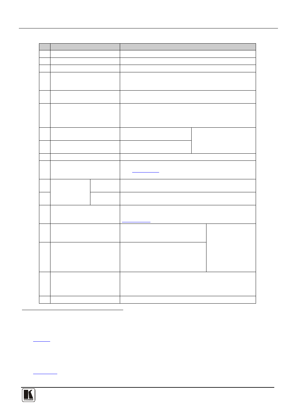
Table 2: VP-8x8TP Front and Rear Panel Features
#
Feature
Function
1
IR Receiver
Receiver for the infrared remote control transmitter
2
IR LED
LED lights yellow when the unit receives IR commands
3
SELECTOR OUT Buttons
Press to select the output
4
to which the input is switched
SELECTOR IN Buttons
Press to select the input to switch to the output (after
selecting an output). When a signal is detected on an input
connector, the corresponding input button lights
5
ALL Button
Press ALL followed by an INPUT button to connect that input to
all outputs
6
OFF Button
Press an OUTPUT button and then the OFF button to
disconnect the selected output from the input.
Press the ALL button and then the OFF button to disconnect
all the outputs
7
VIDEO Button
Press to modify video related
actions
Press VIDEO and AUDIO
together to set the video
switching delay
8
AUDIO Button
Press to modify audio related
actions
9
AFV button
Press to make audio channels follow the video channels
10 AUDIO LEVEL Button
Press to show the relative audio level on the STATUS display
(see
Section 7.1.2
). Select an input, then use the + and –
buttons to change the audio gain level
11
AUDIO LEVEL
+ button
Press to increase the audio input gain
12
(first press Audio
Level and then select an input)
– button
Press to decrease the audio input gain
(first press Audio
Level and then select an input)
13 STATUS 7-segment Display
Displays either the input/output configuration, the audio gain
setting or the firmware build and machine number (see
Section 7.1.2)
14 STO (Store) Button
Press STO followed by an
INPUT/OUTPUT button to store the
setting
Press STO and RCL
together to set the
RS-485 bus
machine number
15
RCL (Recall) Button
Press the RCL button to cause the
corresponding input/output button to
recall a setup from the non-volatile
memory. Press the RCL button again to
implement the new status
16 TAKE Button
Press TAKE to toggle between the Confirm mode
17
and the
At Once mode (user confirmation per action is
unnecessary). When in Confirm mode, press the TAKE
button to implement a pending configuration
LOCK Button
Press and hold to toggle locking of the front panel buttons
1 From 1 to 8
2 For example, press ALL and then Input button # 2 to connect input # 2 to all the outputs
3 The VIDEO button lights when in breakaway mode and actions relate to video
4 See
Section 8
5 The AUDIO button lights when in breakaway mode and actions relate to audio
6 In the case where the Audio Level button was pressed, and the audio level is shown on the Status 7-segment Status Display
7 For example, press STO and then the output button # 3 to store in Setup # 3, or the input button 4 to store in Setup 12
8 See
9 When in the Confirm mode, the TAKE button lights