Kramer Electronics VP-8x8TP User Manual
Page 12
KRAMER: SIMPLE CREATIVE TECHNOLOGY
Defining the VP-8x8TP 8x8 UXGA/Audio Matrix Switcher
8
#
Feature
Function
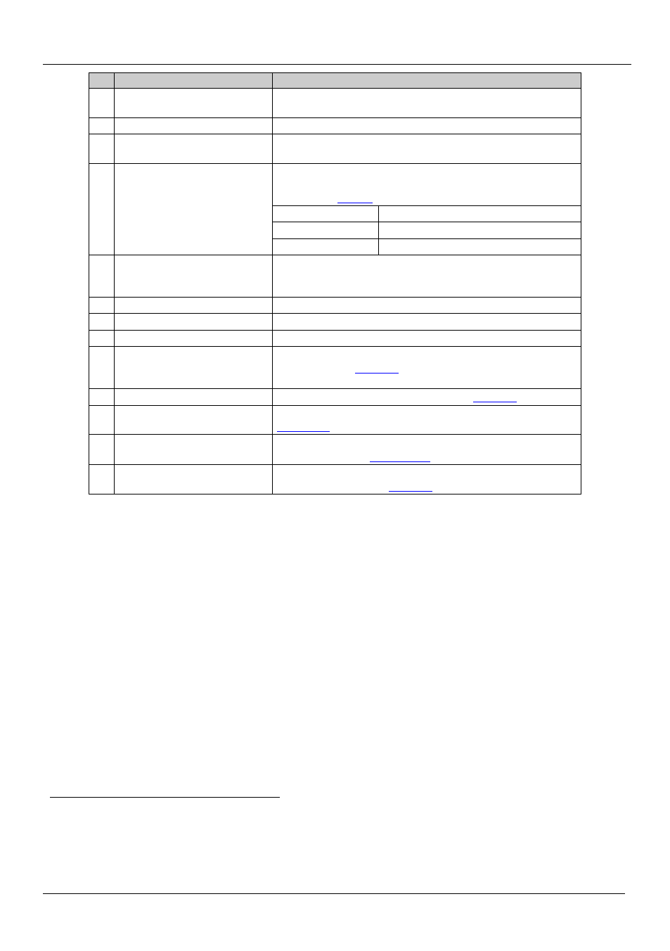
18 VIDEO INPUT 15-pin HD (F)
UXGA Connectors
Connect to the video sources (from 1 to 8)
19 OUT RJ-45 Connectors
Connect to TP receivers (from 1 to 8), for example, TP-122
20 AUDIO INPUT 3.5mm Mini
Jacks
Connect to the unbalanced stereo audio sources (from 1 to 8)
21 FACTORY RESET Button
Press and hold while powering up the unit to reset the audio,
switching, EDID and Ethernet settings to their factory default
values (see
IP Address:
192.168.1.39
Mask:
255.255.255.0
Gateway:
192.168.1.1
22 REMOTE IR Socket
Connect to an external IR receiver unit for controlling the
machine via an IR remote controller instead of using the front
panel IR receiver
23
Power Connector Socket
Connect to the AC mains power
24 Power Connector Fuse
AC mains power fuse
25 Power Switch
Turns the AC mains power ON/OFF
26 PROG Button
Push in for “Program” to upgrade to the latest Kramer firmware
via RS-232 (see
Section 8
), or release for “Normal” operation
(the factory default)
27 RS-232 Terminal Block
Connect to a PC or remote controller (see
Section 8
28 RS-485 Terminal Block
Connect to another RS-485-equiped device for control (see
Section 6.2
29 RS-485 TERM DIP-switch
RS-485 bus termination
: ON to terminate with 120
Ω, OFF for
no termination (see
Section
30 ETHERNET Connector
Connect to a PC or other serial controller through the computer
network for control (see
Section 8
1 Covered by a cap. The 3.5mm mini connector at the end of the internal IR connection cable fits through this opening
2 Optional. Can be used instead of the front panel (built-in) IR receiver to remotely control the machine (only if the internal IR
connection cable has been installed)
3 The first and the last units on the RS-485 line should be terminated (ON). Other units should be unterminated (OFF)