Horizontal installation, Heat controller, inc. hbh series iom manual – Comfort-Aire HBH Series 6-10 Tons User Manual
Page 7
Heat Controller, Inc.
HBH SERIES
IOM Manual
6
Horizontal Installation
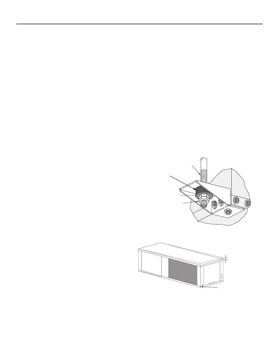
Figure 1: Hanger Bracket
Figure 2: Horizontal Unit Pitch
3/8" [10mm] Threaded
Rod (by others)
Vibration Isolator
(factory supplied)
Washer
(by others)
Double Hex Nuts
(by others)
Varilla Roscada de 3/8"
(fabricada por terceros)
Arandela
(fabricada por terceros)
Tuercas Hexagonales
Dobles (por terceros)
Instale los Tornillos como
se Indica en el Diagrama
La longitud de este tornillo
debe ser de solamente 1/2” para evitar daños
Aislador de Vibraciones
(para codificación por color y
notas de instalación, consulte
las instrucciones de
instalación del soport
e colgador)
1/4" [6.4mm] pitch
for drainage
Drain
Connection
Horizontal Unit Location - Units are not designed for
outdoor installation. Locate the unit in an INDOOR area
that allows enough space for service personnel to perform
typical maintenance or repairs without removing unit from
the ceiling. Horizontal units are typically installed above
a false ceiling or in a ceiling plenum. Never install units in
areas subject to freezing or where humidity levels could
cause cabinet condensation (such as unconditioned
spaces subject to 100% outside air). Consideration should
be given to access for easy removal of the filter and
access panels. Provide sufficient room to make water,
electrical, and duct connection(s). Allow 3 feet (91 cm)
clearance for servicing unit through all access panels.
If the unit is located in a confined space, such as a closet,
provisions must be made for return air to freely enter the
space by means of a louvered door, etc. Any access panel
screws that would be difficult to remove after the unit is
installed should be removed prior to setting the unit. Refer
to Figure 3 for an illustration of a typical installation. Refer
to unit submittal data or engineering design guide for
dimensional data.
Conform to the following guidelines when selecting
unit location:
1. Provide a hinged access door in concealed-spline
or plaster ceilings. Provide removable ceiling
tiles in T-bar or lay-in ceilings. Refer to horizontal
unit dimensions for specific series and model in
unit submittal data. Size the access opening to
accommodate the service technician during the
removal or replacement of the compressor and the
removal or installation of the unit itself.
2. Provide access to hanger brackets, water valves
and fittings. Provide screwdriver clearance to
access panels, discharge collars and all electrical
connections.
3. DO NOT obstruct the space beneath the unit with
piping, electrical cables and other items that prohibit
future removal of components or the unit itself.
4. Use a manual portable jack/lift to lift and support the
weight of the unit during installation and servicing.
The installation of water source heat pump units and all
associated components, parts and accessories which
make up the installation shall be in accordance with
the regulations of ALL authorities having jurisdiction
and MUST conform to all applicable codes. It is the
responsibility of the installing contractor to determine and
comply with ALL applicable codes and regulations.
Mounting Horizontal Units - Horizontal units have hanger
kits pre-installed from the factory as shown in Figure 1.
Figure 3 shows a typical horizontal unit installation.
Horizontal heat pumps are typically suspended above a
ceiling or within a soffit using field supplied, threaded rods
sized to support the weight of the unit.
Use four (4) field supplied threaded rods and factory
provided vibration isolators to suspend the unit. Hang the
unit clear of the floor slab above and support the unit by
the mounting bracket assemblies only. DO NOT attach the
unit flush with the floor slab above.
Pitch the unit toward the drain as shown in Figure 2 to
improve the condensate drainage.