Water-loop heat pump applications, Horizontal installation, Heat controller, inc. hbh series iom manual – Comfort-Aire HBH Series 6-10 Tons User Manual
Page 13: Figure 8: typical water-loop application, Figure 3: typical horizontal unit installation
Heat Controller, Inc.
HBH SERIES
IOM Manual
12
Water-Loop Heat Pump Applications
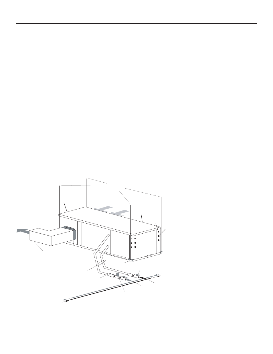
Figure 8: Typical Water-Loop Application
(by others)
Thermostat
Wiring
Insulated supply duct with
at least one 90 deg elbow
to reduce air noise
Return Air
Supply Air
Unit Hanger
3/8" [10mm] threaded rods
Flexible Duct
Connector
Optional
Balancing Valve
Water Out
Optional Low Pressure Drop Water
Control Valve
(can be internally mounted
on some models)
Stainless steel braid hose
with integral ÒJÓ swivel
Building
Loop
HORIZONTAL INSTALLATION
Figure 3: Typical Horizontal Unit Installation
Water In
Ball valve with optional
integral P/T plug
Unit
Power
CAP
CAP
EAP
BSP
CBP
Commercial Water Loop Applications -
Commercial systems typically include a number of units
connected to a common piping system. Any unit plumbing
maintenance work can introduce air into the piping system;
therefore air elimination equipment is a major portion of the
mechanical room plumbing. In piping systems expected to
utilize water temperatures below 50°F [10°C], 1/2” (13mm)
closed cell insulation is required on all piping surfaces to
eliminate condensation (extended range units required).
Metal to plastic threaded joints should never be used due to
their tendency to leak over time. All commercial class units
include low temperature-soldered bracket-supported IPT
water connections, which do not require a backup wrench.
Teflon tape thread sealant is recommended to minimize
internal fouling of the heat exchanger. Do not over tighten
connections and route piping so as not to interfere with
service or maintenance access. Hose kits are available
from Heat Controller in different configurations as shown
in Figure 8 for connection between the unit and the piping
system. Depending upon selection, hose kits may include
shut off valves, P/T plugs for performance measurement,
high pressure stainless steel braided hose, “Y” type strainer
with blow down valve, and/or “J” type swivel connection.
Balancing valves and an external low pressure drop solenoid
valve for use in variable speed pumping systems may also
be included in the hose kit.
The piping system should be flushed to remove dirt, piping
chips, and other foreign material prior to operation (see
“Piping System Cleaning and Flushing Procedures” in this
manual). The flow rate is usually set between 2.25 and 3.5
gpm per ton [2.9 and 4.5 l/m per kW] of cooling capacity.
Heat Controller recommends 3 gpm per ton [3.9 l/m per kW]
for most applications of water loop heat pumps. To insure
proper maintenance and servicing, P/T ports are imperative
for temperature and flow verification, as well as performance
checks.
Water loop heat pump (cooling tower/boiler) systems
typically utilize a common loop, maintained between 60 -
90°F [16 - 32°C]. The use of a closed circuit evaporative
cooling tower with a secondary heat exchanger between the
tower and the water loop is recommended. If an open type
cooling tower is used continuously, chemical treatment and
filtering will be necessary.
Low Water Temperature Cutout Setting
- CXM Control
When antifreeze is selected, the FP1
jumper (JW3) should be clipped to
select the low temperature (antifreeze
10°F [-12.2°C]) set point and avoid
nuisance faults (see “Low Water
Temperature Cutout Selection” in this
manual).
Note: Low water temperature operation
requires extended range equipment.