Functional troubleshooting - i.p. units, Heat controller, inc. hbh series iom manual, Refrigerant circuit diagrams – Comfort-Aire HBH Series 6-10 Tons User Manual
Page 45
Heat Controller, Inc.
HBH SERIES
IOM Manual
44
Functional Troubleshooting - I.P. Units
Note: Never connect refrigerant gauges during startup procedures. Conduct water-side analysis using P/T ports to determine
water flow and temperature difference. If water-side analysis shows poor performance, refrigerant troubleshooting may be
required. Connect refrigerant gauges as a last resort.
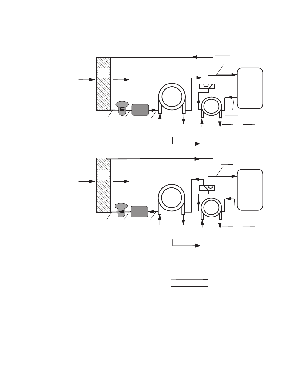
Packaged Unit Refrigeration Schematic
Rev. 12/08
Customer: _____________________________________ Antifreeze: ________________________
Model#: ________________________ Serial#: ________________ Loop type: _______________
Complaint: ________________________________________________________________________
COAX
COMPRESSOR
DISCHARGE
SUCTION
HWG
COOLING CYCLE ANALYSIS -
COAX
COMPRESSOR
DISCHARGE
SUCTION
HWG
HEATING CYCLE ANALYSIS -
PSI
SAT
PSI
SAT
°
F
°
F
AIR
COIL
°
F
°
F
FP2: HEATING
LIQUID LINE
°
F
EXPANSION
VALVE
AIR
COIL
°
F
°
F
PSI
SAT
PSI
SAT
°
F
°
F
°
F
°
F
WATER IN
WATER OUT
PSI
PSI
°
F
°
F
WATER IN
WATER OUT
PSI
PSI
Use 500 for water, 485 for antifreeze.
FILTER
DRIER*
FLASH
GAS LINE
°
F
FP1
SENSOR
°
F
EXPANSION
VALVE
FILTER
DRIER*
FP2: FLASH
GAS LINE
°
F
OTHER SIDE
OF FILTR DR
°
F
FP1: CLG
LIQ LINE
°
F
Refrigerant Type:
HFC-410A
Heat of Extraction (Absorption) or Heat of Rejection =
________
flow rate (
diff. (
factor = _____________
(Btu/hr)
Superheat
Subcooling
Suction temperature - suction saturation temp.
Discharge saturation temp. - liquid line temp.
=
=
=
=
(deg F)
(deg F)
gpm) x ________ temp.
deg. F) x ________ fluid
Date: ________________________
Voltage: ________
Comp Amps: _______
Total Amps: ________
Location: ________________________
Model Number: ________________________
Serial Number: ________________________
Look up pressure drop in
I.O.M. or spec. catalog to
determine flow rate.
Look up pressure drop in
I.O.M. or spec. catalog to
determine flow rate.
Refrigerant Circuit Diagrams