Electrical - power & low voltage wiring – Comfort-Aire HBH Series 6-10 Tons User Manual
Page 21
Heat Controller, Inc.
HBH SERIES
IOM Manual
20
Electrical - Power & Low Voltage Wiring
ELECTRICAL - LOW VOLTAGE WIRING
Figure 12: HBH 072-120 Low Voltage Field Wiring
Thermostat Connections - The thermostat should be
wired directly to the CXM board. Figure 12 shows wiring
for units. See “Electrical – Thermostat” (Figure 16) for
specific terminal connections.
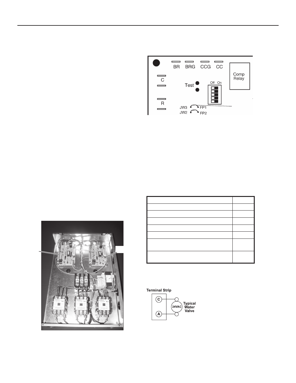
Low Water Temperature Cutout Selection - The CXM
control allows the field selection of low water (or water-
antifreeze solution) temperature limit by clipping jumper
JW3, which changes the sensing temperature associated
with thermistor FP1. Note that the FP1 thermistor is
located on the refrigerant line between the coaxial heat
exchanger and expansion device (TXV or cap tube).
Therefore, FP1 is sensing refrigerant temperature, not
water temperature, which is a better indication of how
water flow rate/temperature is affecting the refrigeration
circuit.
The factory setting for FP1 is for systems using water
(30°F [-1.1°C] refrigerant temperature). In low water
temperature (extended range) applications with antifreeze
(most ground loops), jumper JW3 should be clipped as
shown in Figure 13 to change the setting to 10°F [-12.2°C]
refrigerant temperature, a more suitable temperature
when using an antifreeze solution. All Heat Controller units
operating with entering water temperatures below 59°F
[15°C] must include the optional water/refrigerant circuit
insulation package to prevent internal condensation.
CXM1 Low
Voltage
Connector
CXM2
Figure 13: FP1 Limit Setting
CXM PCB
JW3-FP1
jumper should
be clipped for
low temperature
operation
Figure 14: Accessory Wiring
Low Voltage VA Ratings
Components In Unit
VA
Typical Blower Contactor
6 - 9
Typical Reversing Valve Solenoid (2)
8 - 12
30A Compressor Contactor (2)
12 - 18
CXM board (2)
10 - 18
DXM board (2)
16 - 24
Units with CXM
Remaing VA for Accessories
39 - 18
Units with DXM
Remaing VA for Accessories
33 - 12
Standard transformer is 75VA.
Accessory Connections - A terminal paralleling the
compressor contactor coil has been provided on the CXM
control. Terminal “A” is designed to control accessory
devices, such as water valves. Note: This terminal should
be used only with 24 Volt signals and not line voltage.
Terminal “A” is energized with the compressor contactor.
See the specific unit wiring diagram for details.