Electrical - low voltage wiring – Comfort-Aire HBH Series 6-10 Tons User Manual
Page 22
IOM Manual
HBH SERIES
Heat Controller, Inc.
21
Electrical - Low Voltage Wiring
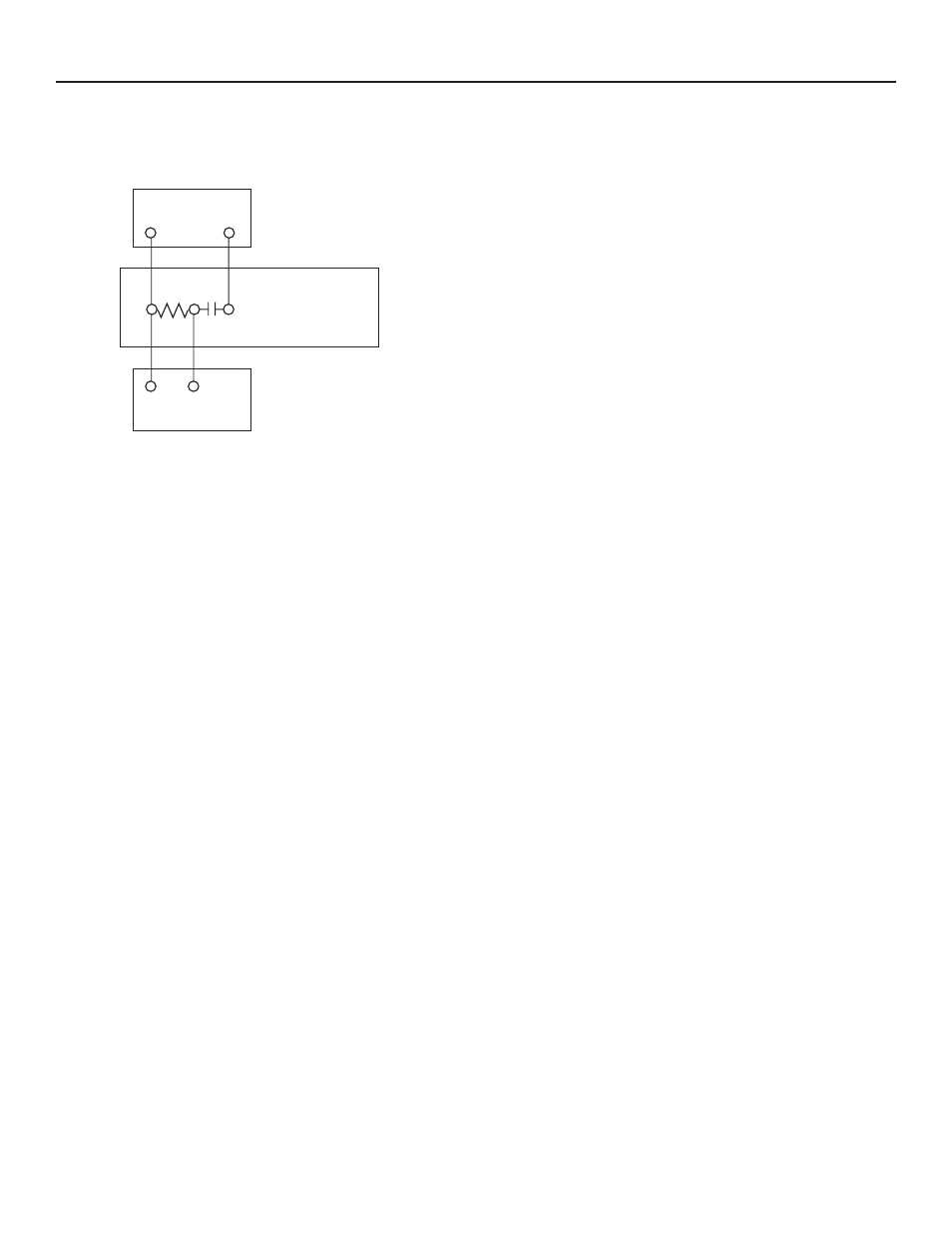
Figure 15: Optional Motorized Water Valve Wiring
C
C
Thermostat
Y1
1
2
3
Y1
23B0040N01
for 072 and 096
or 23B0041N01
for 120 Valve
Switch
Water Solenoid Valves - An external solenoid valve(s)
should be used on ground water installations to shut off
flow to the unit when the compressor is not operating. A
slow closing valve may be required to help reduce water
hammer. Figure 14 shows typical wiring for a 24VAC
external solenoid valve. This wiring should only be used
if valve fully opens in 15 second. Figure 15 illustrates
a typical slow closing water control valve wiring for
Belimo valves. Slow closing valves take approximately
60 seconds to open (very little water will flow before 45
seconds). Once fully open, an end switch allows the
compressor to be energized. Only relay or triac based
electronic thermostats should be used with slow closing
valves. When wired as shown, the slow closing valve will
operate properly with the following notations:
1.
The valve will remain open during a unit
lockout.
2.
The valve will draw approximately 25-35 VA
through the “Y” signal of the thermostat.
Note: This valve can overheat the anticipator of an
electromechanical thermostat. Therefore, only relay or
triac based thermostats should be used.