Unit operating conditions, Heat controller, inc. hbh series iom manual, Based on 15% methanol antifreeze solution – Comfort-Aire HBH Series 6-10 Tons User Manual
Page 41
Heat Controller, Inc.
HBH SERIES
IOM Manual
40
Unit Operating Conditions
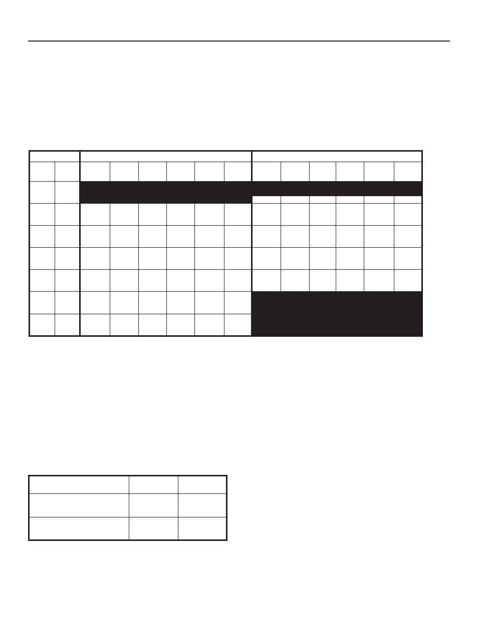
Table 11: HB Series Typical Unit Operating Pressures and Temperatures (60Hz - I.P. Units)
Operating Pressure/Temperature tables include the
following notes:
• Airflow is at nominal (rated) conditions;
• Entering air is based upon 70°F [21°C] DB in heating
and 80/67°F [27/19°C] in cooling;
• Subcooling is based upon head pressure at compressor
service port;
• Cooling air and water values can vary greatly with
changes in humidity level.
Cooling
Heating
Entering
Water
Temp °F
Water
Flow
GPM/ton
Suction
Pressure
PSIG
Discharge
Pressure
PSIG
Superheat
Subcooling
Water
Temp Rise
°F
Air Temp
Drop °F
DB
Suction
Pressure
PSIG
Discharge
Pressure
PSIG
Superheat Subcooling
Water
Temp Drop
°F
Air Temp
Rise °F DB
20
1.5
2.25
3
60 - 63
289 - 306
9 - 12
8 - 17
3 - 4
20 - 22
30
*
1.5
2.25
3
122 - 125
116 - 119
112 - 115
197 - 204
177 - 184
168 - 173
13 - 16
17 - 19
19 - 21
15 - 20
15 - 18
14 - 18
20 - 24
13 - 16
10 - 12
22 - 23
21 - 22
21 - 22
67 - 71
71 - 75
74 - 76
297 - 315
301 - 321
303 - 323
10 - 12
10 - 12
11 - 13
9 - 18
10 - 19
10 - 19
8 - 9
6 - 7
4 - 5
22 - 23
23 - 24
23 - 25
50
1.5
2.25
3
128 - 134
122 - 131
119 - 129
240 - 252
219 - 233
209 - 224
11 - 14
12 - 17
13 - 18
13 - 16
12 - 16
11 - 15
20 - 22
13 - 15
10 - 11
21 - 22
21 - 22
21 - 22
97 - 102
104 - 108
107 - 122
333 - 355
339 - 361
342 - 369
9 - 11
9 - 11
9 - 11
13 - 21
13 - 21
13 - 20
11 - 12
8 - 9
6 - 7
29 - 30
30 - 31
31 - 32
70
1.5
2.25
3
132 - 139
131 - 137
131 - 136
311 - 329
287 - 306
275 - 294
9 - 12
10 - 13
10 - 13
12 - 15
10 - 12
9 - 11
19 - 21
13 - 14
9 -11
20 - 21
20 - 21
20 - 21
130 - 135
139 - 144
145 - 149
367 - 392
375 - 402
380 - 407
9 - 11
10 - 11
10 - 11
13 - 21
13 - 20
13 - 19
14 - 16
10 - 12
8 - 9
35 - 37
37 - 38
38 - 39
90
1.5
2.25
3
137 - 144
135 - 142
135 - 141
400 - 420
373 - 395
359 - 383
8 - 10
9 - 11
9 - 12
13 - 16
10 - 12
9 - 11
19 - 20
12 - 14
9 - 10
19 - 20
19 - 20
19 - 20
164 - 169
175 - 178
179 - 187
401 - 430
411 - 442
415 - 455
10 - 13
12 - 16
13 - 18
13 - 17
14 - 17
14 - 16
18 - 20
12 - 14
9 - 11
41 - 43
43 - 45
44 - 46
100
1.5
2.25
3
139 - 147
138 - 146
138 - 146
448 - 471
420 - 445
405 - 432
8 - 9
8 - 10
8 - 10
13 - 16
11 - 13
10 - 11
18 - 20
12 - 13
9 - 10
18 - 19
18 - 19
18 - 19
120
1.5
2.25
3
144 - 153
143 - 153
143 - 152
549 - 583
525 - 557
511 - 543
7 - 8
7 - 8
8 - 9
15 - 17
12 - 14
11 - 13
17 - 19
11 - 13
9 - 10
17 - 18
17 - 18
17 - 18
*Based on 15% Methanol antifreeze solution
NOTE: The tables include the following notes:
•
Airflow is at nominal (rated) conditions;
•
Entering air is based upon 70°F [21°C] DB in heating and
80/67°F [27/19°C] in cooling;
•
Subcooling is based upon head pressure at compressor
service port;
•
Cooling air and water values can vary greatly with
changes in humidity level.
Table 12: Water Temperature Change Through Heat
Exchanger
Water Flow, gpm [l/m]
Rise, Cooling
°F, [°C]
Drop, Heating
°F, [°C]
For Closed Loop: Ground Source or
Closed Loop Systems at 3 gpm per
ton [3.2 l/m per kW]
9 - 12
[5 - 6.7]
4 - 8
[2.2 - 4.4]
For Open Loop: Ground Water
Systems at 1.5 gpm per ton
[1.6 l/m per kW]
20 - 26
[11.1 - 14.4]
10 - 17
[5.6 - 9.4]