Pulsafeeder PulsaPro 900 EN User Manual
Page 70
68
3.1
The
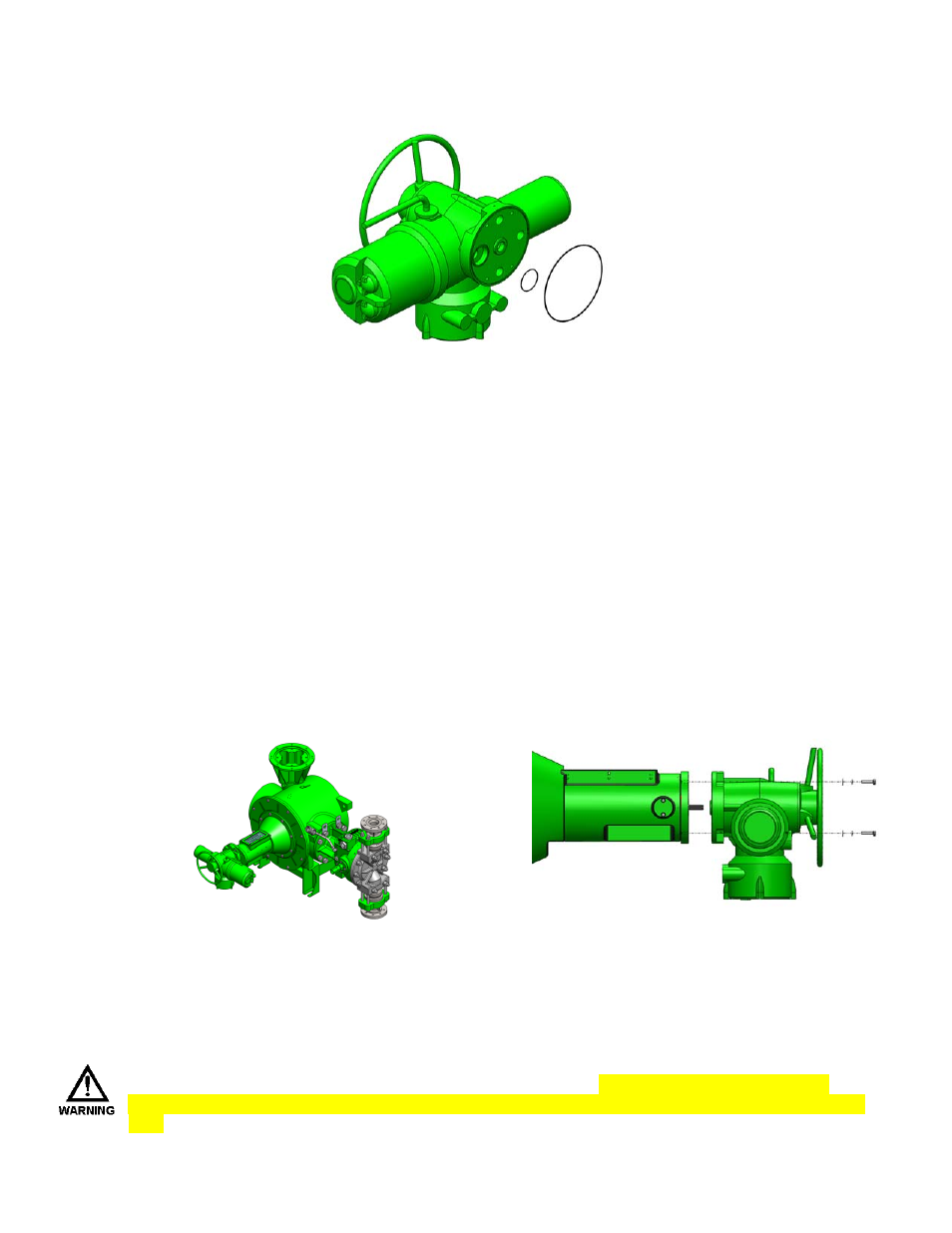
stroke control unit is supplied with 2 sealing O-rings; these o-rings must be installed prior to mounting of
the stroke control unit. Refer to illustration below. See Figure A
Figure A
3.2
Remove Red
plastic shipping cap from the pumps stroke adjust housing matting face prior trying to bolt the unit
into place.
3.3
Reference Figure B:
Properly supporting
the stroke control unit lift the stroke control unit into place so the splined pump input shift is lined up
with the female spline in the controller unit. Using caution to avoid putting stress or any excessive loading on the shaft,
slide unit into place until the 2 mounting faces are flush or mated. Install the Qty 4 M8 bolts with flat washers and lock
washers. Torque bolts to 16 ft lbs / 70 nm.
Figure B
Installation of the stroke controller to pump is now completed. Please refer to Rotork’s IOM E170E3 for wiring and setup
of additional features such as 4-20 Ma input/ouput, alarms and other IO that you might require.
When conducting the final wiring or setup of additional IO features, DON’T ALTER ANY POSTION
SETTINGS OR PRESET FACTORY TORQUE LIMITS. Doing so will cause damage to the stroke control
unit.