5 hydraulic bypass valve (hbv) – Pulsafeeder PulsaPro 900 EN User Manual
Page 35
31
Figure 16
10. Reinstall the diaphragm and the reagent head using the procedure outlined in Section 7.1.
11. Close the Gearbox / Pump Head drain valve and fill with PULSAlube Universal or Ultra
hydraulic oil.
12. Re-prime the pump head.
7.5
Hydraulic Bypass Valve (HBV)
All
PulsaPro
Series pumps incorporate a Hydraulic Bypass Valve (HBV). This valve is
designed to protect the pump against excessive hydraulic pressure encountered during system
upset (it will not limit or regulate system pressure). It is constructed of an adjustable spring
loaded valve ported into the hydraulic cavity of the pump head. The valve is factory-set at 10%
above the rated pump discharge pressure or as specified at the time of order.
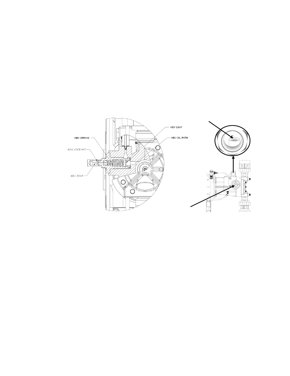
Figure 17
The HBV is located on the left side of the pump head as you face the reagent head. Discharge
from this valve is visible through a large diameter tube located behind the diagnostic port that
faces the same side of the pump (refer to figure 17). Whenever discharge is visible, it indicates
the pressure in the pump discharge piping exceeds the HBV setting. After confirming the
discharge pressure is within the rated pressure of the pump it may be necessary to adjust the
HBV setting.
Adjusting the HBV Valve:
1. Remove the valve adjustment cover.
2. Loosen the locknut.
3. Tighten the adjustment bolt by turning clockwise (as seen facing the screw) to increase
the bypass pressure. Loosen the bolt by turning counterclockwise to decrease it.
4. Re-tighten the locknut after adjustment.
5. Re-install the valve adjustment cover.
Pump damage may occur during a system upset if the hydraulic bypass pressure is set higher
than 10% over the design pressure of the pump (refer to the nameplate rating). Conversely, if
ADJUST
HBV
HERE
OBSERVE
HBV FLOW
HERE